FIG. 01
RECORD DATA
Category
Avionics
DATE
The most maddening failure in a field test is the one that doesn't look like a failure: the HUD in Mission Planner freezes, comes back a few seconds later, then freezes again. The aircraft keeps flying, but you no longer know where it is. The first time we saw this, our reflex was "let's get a stronger radio". That was the wrong reflex.
Because there are two separate problems here, and they don't want the same solution. The telemetry link carries a few kilobytes per second but it must not drop; the video link carries megabits per second but can live with the odd lost frame. Filing both under a single "wireless link" heading is the fastest way to end up doing both of them badly.
In this post we walk through the decision chain we followed while building our SUAS 2026 aircraft: which band we picked and why, how we worked the link budget out line by line, and why the numbers on paper didn't hold up in the field.
Two different jobs, two different links
Telemetry | Video | |
|---|---|---|
Typical data rate | a few kB/s | on the order of Mbit/s |
Latency tolerance | hundreds of milliseconds | depends on the mission, low is preferred |
Packet loss tolerance | low (a lost command is critical) | high (a frame drops, the flight goes on) |
What happens if it cuts out | failsafe / RTL | the operator loses the picture |
Priority | reliability | bandwidth |
Let's put numbers on it. At ArduPilot's default MAVLink stream rates (4 Hz) the flight controller produces roughly 3.5–4 kB/s; a 57600 baud serial line carries only a little more than that, which puts the link at 59–69% utilization. Dropping the streams to 1 Hz brings that down to ~0.9–1.0 kB/s, and switching off the groups you don't need takes it to ~0.6–0.8 kB/s.
The real trap here is error correction (ECC) on the SiK radios: with it on, the throughput you can actually carry falls by about half. At the default 64 kbps air rate with ECC enabled you are left with an effective ~32 kbps ≈ 4 kB/s, meaning the link sits right on the edge at default stream rates. If you plan to drop the air rate for range and keep ECC on, you have to drop the stream rates too:
Leave SR1_PARAMS alone. MAVLink v2 framing overhead is 12 bytes per packet (25 if signed) and the maximum frame is 280 bytes; on small messages that overhead is a big fraction of the packet, so switching off the groups you don't need buys you far more than sending "a handful of messages at a high rate".
Frequency band: the trade between range and bandwidth
Band | Typical use | Strength | Weakness | When |
|---|---|---|---|---|
433 MHz | Telemetry | Gets past obstacles better, longer range at the same power | Narrow band, heavy amateur radio noise | Long range, when a low data rate is enough |
868 / 915 MHz | Telemetry | Good range-versus-bandwidth balance, mature ecosystem | Band differs by region (868 vs 915) | Standard telemetry link |
2.4 GHz | RC + Wi-Fi video | Wide bandwidth, cheap hardware | The most crowded band there is; risk of clashing with RC | Short range, high data rate |
5.8 GHz | Video | Very wide bandwidth, well clear of RC and telemetry | Short range, heavily dependent on line of sight | Video link |
Rule of thumb: as frequency goes up, bandwidth goes up while range and the ability to punch through obstacles go down. That is why the common setup keeps telemetry in sub-GHz, video at 5.8 GHz and RC at 2.4 GHz: three jobs on three separate bands.
On the hardware side: SiK v2 radios cover 414–454 MHz on the 433 model and 895–935 MHz on the 900 model, put out at most 20 dBm (100 mW), and let you set the air data rate anywhere from 2 to 250 kbps. The RFD900x datasheet quotes +30 dBm (1 W) output, receiver sensitivity better than −121 dBm at low rates, and air rates up to 500 kbps. The manufacturer talks about ranges past 40 km depending on antennas and configuration; don't treat that number as a guarantee for your own setup.
Regulatory note: in Turkey, license-exempt operation is defined by BTK's Regulation on Radio Equipment and Systems Exempt from Frequency Allocation (Frekans Tahsisinden Muaf Telsiz Cihaz ve Sistemleri Hakkında Yönetmelik, 27 November 2018) and the technical criteria document that goes with it. We are not going to write down here which band is exempt at which power limit; bands and power limits get revised, so check BTK's current technical criteria document before you buy. Competition rules can impose band restrictions of their own on top of that. The MIN_FREQ, MAX_FREQ, NUM_CHANNELS, DUTY_CYCLE and LBT_RSSI registers in the SiK firmware exist for exactly this kind of compliance. Don't assume the module's factory settings are "probably fine".
The link budget: knowing how many dB you have
A link budget is a one-line sum. Free-space path loss (FSPL):
FSPL(dB) = 32.44 + 20·log10(f_MHz) + 20·log10(d_km)
P_rx(dBm) =P_tx+G_tx_antenna+G_rx_antenna
− cable/connector loss −FSPLFade margin =
P_rx−receiver_sensitivity
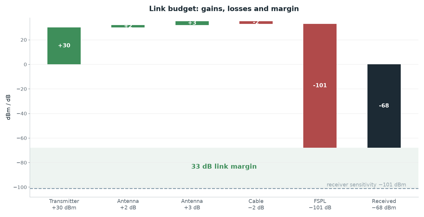
Worked example: 915 MHz, 3 km, an RFD900x-class radio.
FSPL term | Value |
|---|---|
20·log10(915) | 59.23 dB |
20·log10(3) | 9.54 dB |
FSPL = 32.44 + 59.23 + 9.54 | 101.2 dB |
Received power term | Value |
|---|---|
Transmitter | 30 dBm |
Aircraft dipole | +2 dBi |
Ground antenna | +3 dBi |
Cable + connectors | −2 dB |
Free-space path loss | −101.2 dB |
| −68.2 dBm |
Fade margin = −68.2 − (−121) | 52.8 dB |
Fifty-two dB of margin. So why can the very same setup lose the link at 500 meters? Because there are line items this sum never sees: the noise floor thrown off by the ESCs and the companion computer, antenna orientation, airframe shadowing, multipath fading. A link budget gives you the upper bound, not the performance you get in the field.
Here is what it is genuinely good for: double the distance and FSPL rises by 6 dB. So every 6 dB of improvement you can find (antenna gain, a shorter cable, a lower air rate) doubles your theoretical range. That is how you see that a 3 dBi antenna upgrade does not mean "it helps a little", it means "about 40% more range".
The Fresnel zone: "I can see it" isn't enough
A radio wave doesn't travel between two antennas as a thin line; it fills an ellipsoidal volume. That volume is the first Fresnel zone, and at least 60% of it has to be clear of obstructions. Around 20% blockage costs you nothing worth mentioning; once you get past 40%, the loss climbs fast.
r_max(m) = 17.32 · sqrt(D_km/ (4 ·f_GHz) ), the radius at the midpoint of the path
Link | Radius at midpoint | 60% of it |
|---|---|---|
915 MHz, 3 km | 17.32 · sqrt(3 / 3.66) = 15.7 m | ≈ 9.4 m |
5.8 GHz, 1 km | 17.32 · sqrt(1 / 23.2) = 3.6 m | ≈ 2.2 m |
At 915 MHz over a 3 km path we want 9 meters of clearance at the midpoint. A tree line, a rise in the ground, a parked van: they all count. That is exactly what the ArduPilot documentation is getting at when it tells you to put the ground station antenna clear of obstructions and a few meters off the ground, building a stand if you have to. Setting the antenna on a table and sitting down beside it means putting your own body inside the Fresnel zone.
Antenna types and polarization
Type | Gain | Pattern | When |
|---|---|---|---|
Dipole / omni | low (~2–3 dBi) | Omnidirectional, null straight overhead | On the aircraft; when you don't know the direction |
Patch | medium | Wide beam in one direction | At the ground station, when you know the flight area |
Yagi / helical | high | Narrow beam | Long range, if you can keep it pointed at the target |
A half-wave dipole radiates maximum broadside to the conductor and nothing along the conductor's axis. On multirotors this matters: mount the antenna vertically on the airframe, then fly the aircraft directly over the ground station, and the two antennas point their nulls straight at each other, and the signal collapses at the shortest range of the whole flight. That is the classic cause behind "it works far out, it drops when it's over my head".
Polarization matching is a line item of its own: a vertically polarized antenna working against a horizontally polarized one takes a serious mismatch loss. Use the same polarization at both ends; the match will fall apart on its own as the aircraft banks, so don't start out mismatched.
The video link and latency
On the video side the decision runs along two axes: analog or digital, and how much latency you can afford. Analog FPV links keep latency very low, but the image quality isn't good enough for detection. Digital links (Wi-Fi based systems, gimbal cameras that serve RTSP, proprietary HD systems) give you a clean picture; the price is the latency that comes out of the encode-packetize-buffer-decode chain.
In our setup this decision got easy: the SIYI A8 mini gimbal camera hands its 1080p RTSP stream to the Jetson Orin NX over Ethernet, onboard the aircraft. Detection and the airdrop decision are made on the aircraft; the wireless video link exists purely so the operator can watch. In other words, the wireless link's latency is not inside our decision loop. Build that separation into an autonomous mission wherever you can. Don't run your critical loop over a radio wave.
The latency chain works like this: camera encoding → packetization → wireless transport → receiver buffer → decoding → display. The one that surprises people most is the buffer on the receiving end, because it has nothing to do with RF and can add whole seconds. We covered RTSP buffer build-up and the fix for it in detail in processing an RTSP video stream in Python. Measure the software side before you blame the link.
Common traps
Powering up without an antenna. Running a radio with no antenna can permanently damage the output stage. Connect the antenna before you apply power; don't switch it on "just for a second" without one, not even while testing.
Flying the aircraft directly over the ground station. A dipole radiates nothing along its axis. On a calibration flight, pass right over the antenna and watch RSSI; you'll see the notch.
Mounting the telemetry and video antennas side by side. Even on different bands, antennas that close will degrade each other. Separate them as much as you can, and keep the video transmitter away from the GPS and compass too.
Using the same band for RC, telemetry and video. Running both RC and Wi-Fi video on 2.4 GHz puts your critical command channel inside the most crowded band there is.
Running a longer cable and not budgeting the loss. A few meters of thin coax easily eats a few dB. Don't give back in the cable what you gained in antenna gain.
Looking only at RSSI. The ArduPilot documentation recommends graphing
rssi,remrssi,noiseandremnoisetogether:rssiandnoisemeet on the plot exactly where the link drops. If the noise floor is high, the answer is to cut the noise, not to push more signal.Hunting the problem blind in the field. Start with the one-meter test: set the two radios a meter apart and look at local and remote RSSI. If the numbers are bad even there, the problem isn't range, it's the installation.
Raising the data rate and expecting range. Lowering the air rate buys range and costs throughput. You can't ask for both at once.
Practical summary
Design telemetry and video separately, and put them on separate bands. Telemetry on sub-GHz, video on 5.8 GHz, RC on 2.4 GHz is the typical split, and it works.
Write the link budget down, on a single sheet: transmit power + antenna gains − cable loss − FSPL. Twice the distance = 6 dB; every 6 dB you gain doubles theoretical range.
Keep 60% of the Fresnel zone clear. Get the ground station antenna a few meters off the ground and away from obstructions; don't put yourself in front of it.
Manage bandwidth with the stream rates. With ECC on you give up half your air rate; lowering the
SR1_*parameters and turning offSR1_RAW_SENSgives the link room to breathe.Measure before you fly: the one-meter test, then an RSSI/noise plot out at the field. Look for the cause of a link loss in the logs, not in the middle of the flight.
For frequency and power limits, go to BTK's current technical criteria and to the competition rules. A module's factory settings are not a compliance guarantee.