Airframe Core
It starts at the core
The central airframe locks together first: the structural heart that will carry every subsystem of the KA-FA1500.
SUAS 2026 · System Assembly
KA-FA1500
Scroll to build the aircraft, piece by piece.
Carbon Structure
Folding carbon arms
Four 20 mm 3K carbon fiber arms mount on RJX folding joints: rigid in flight, compact on the bench.
Propulsion
T-Motor U7 490KV
Four U7 490KV motors and matched propellers spin onto the arm tips to deliver the thrust behind every mission.
Landing Gear
Telescopic stance
The telescopic landing gear reaches down and locks, a stable footprint for touchdown and takeoff.
Avionics & Power
Cube Orange + ArduPilot
A Cube Orange flight controller running ArduPilot slides into the bay, powered by a Leopard 13000 mAh pack.
Sensors & Delivery
Eyes on the mission
The canopy closes over the avionics as the SIYI A8 mini gimbal and the air delivery mechanism come aboard.
SUAS 2026
KA-FA1500
Assembly complete. Scroll on to meet the aircraft.
TECHNICAL DATA
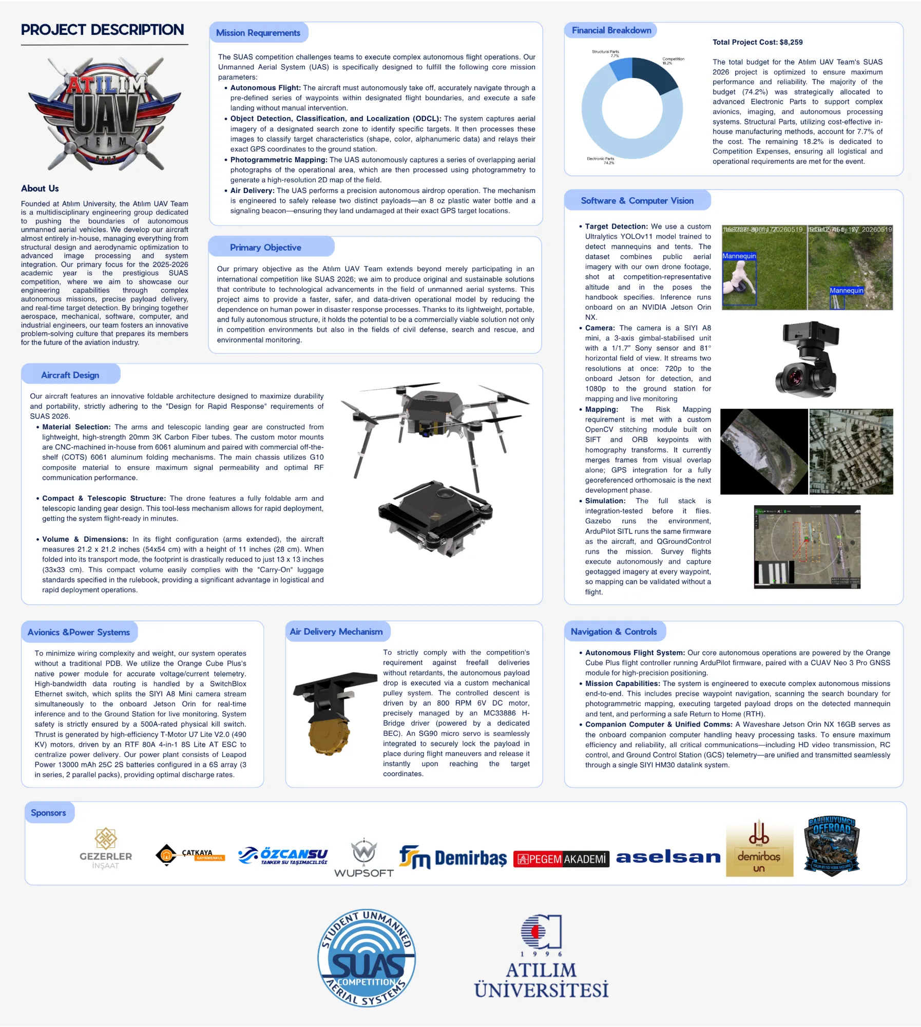
Project Description
About Us
Founded at Atılım University, the Atılım UAV Team is a multidisciplinary engineering group dedicated to pushing the boundaries of autonomous unmanned aerial vehicles. We develop our aircraft almost entirely in-house, managing everything from structural design and aerodynamic optimization to advanced image processing and system integration. Our primary focus for the 2025-2026 academic year is the prestigious SUAS competition, where we aim to showcase our engineering capabilities through complex autonomous missions, precise payload delivery, and real-time target detection. By bringing together aerospace, mechanical, software, computer, and industrial engineers, our team fosters an innovative problem-solving culture that prepares its members for the future of the aviation industry.
Mission Requirements
The SUAS competition challenges teams to execute complex autonomous flight operations. Our Unmanned Aerial System (UAS) is specifically designed to fulfill the following core mission parameters:
- Autonomous Flight: The aircraft must autonomously take off, accurately navigate through a pre-defined series of waypoints within designated flight boundaries, and execute a safe landing without manual intervention.
- Object Detection, Classification, and Localization (ODCL): The system captures aerial imagery of a designated search zone to identify the mannequin and tent targets. It then processes these images with an onboard detector and relays their exact GPS coordinates to the ground station.
- Risk Mapping: The UAS autonomously captures a series of overlapping aerial photographs during the waypoint survey, which our in-house FastMosaic pipeline stitches on site into a single map of the Search Boundary, written directly in the submission-ready image format.
- Air Delivery: The UAS performs a precision autonomous airdrop operation. The mechanism is engineered to safely release two distinct payloads, an 8 oz plastic water bottle and a signaling beacon, ensuring they land undamaged at their exact GPS target locations.
Primary Objective
Our primary objective as the Atılım UAV Team extends beyond merely participating in an international competition like SUAS 2026; we aim to produce original and sustainable solutions that contribute to technological advancements in the field of unmanned aerial systems. This project aims to provide a faster, safer, and data-driven operational model by reducing the dependence on human power in disaster response processes. Thanks to its lightweight, portable, and fully autonomous structure, it holds the potential to be a commercially viable solution not only in competition environments but also in the fields of civil defense, search and rescue, and environmental monitoring.
Financial Breakdown
$8,259Total Cost
Electronic Parts 74.2%
Structural Parts 7.7%
Competition 18.2%
Total Project Cost: $8,259
The total budget for the Atılım UAV Team's SUAS 2026 project is optimized to ensure maximum performance and reliability. The majority of the budget (74.2%) was strategically allocated to advanced Electronic Parts to support complex avionics, imaging, and autonomous processing systems. Structural Parts, utilizing cost-effective in-house manufacturing methods, account for 7.7% of the cost. The remaining 18.2% is dedicated to Competition Expenses, ensuring all logistical and operational requirements are met for the event.
- Target Detection: We use a custom Ultralytics YOLO11m model trained to detect mannequins and tents. The dataset combines public aerial imagery with our own drone footage, shot at competition-representative altitude and in the poses the handbook specifies. Inference runs onboard on an NVIDIA Jetson Orin NX.
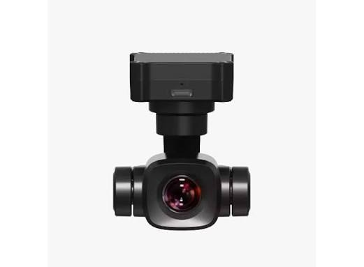
- Camera: The camera is a SIYI A8 mini, a 3-axis gimbal-stabilised unit with a 1/1.7" Sony sensor and 81° horizontal field of view. It streams a single 1080p feed over RTSP, which a SwitchBlox Ethernet switch splits to the onboard Jetson for detection and to the ground station for mapping and live monitoring
- Mapping: The Risk Mapping requirement is met by FastMosaic, our in-house stitching pipeline. GPS-assisted frame selection orders and gates frames from the flight log, ORB feature matching with RANSAC estimates a 4-DOF similarity transform between overlapping frames, and distance-transform feathering blends them into the final map, written directly in the submission-ready PNG format.
- Simulation: The full stack is integration-tested before it flies. Gazebo runs the environment, ArduPilot SITL runs the same firmware as the aircraft, and Mission Planner runs the mission. Survey flights execute autonomously and capture geotagged imagery at every waypoint, so mapping can be validated without a flight.
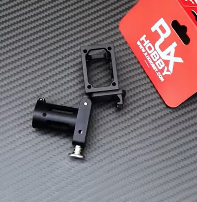
Our aircraft features an innovative foldable architecture designed to maximize durability and portability, strictly adhering to the "Design for Rapid Response" requirements of SUAS 2026.
- Material Selection: The arms and telescopic landing gear are constructed from lightweight, high-strength 20mm 3K Carbon Fiber tubes. The custom motor mounts are CNC-machined in-house from 6061 aluminum and paired with commercial off-the-shelf (COTS) 6061 aluminum folding mechanisms. The main chassis utilizes G10 composite material to ensure maximum signal permeability and optimal RF communication performance.
- Compact & Telescopic Structure: The drone features a fully foldable arm and telescopic landing gear design. This tool-less mechanism allows for rapid deployment, getting the system flight-ready in minutes.
- Volume & Dimensions: In its flight configuration (arms extended), the aircraft measures 21.2 x 21.2 inches (54x54 cm) with a height of 11 inches (28 cm). When folded into its transport mode, the footprint is drastically reduced to just 13 x 13 inches (33x33 cm). This compact volume easily complies with the "Carry-On" luggage standards specified in the rulebook, providing a significant advantage in logistical and rapid deployment operations.

To minimize wiring complexity and weight, our system operates without a traditional PDB. We utilize the Cube Orange Plus's native power module for accurate voltage/current telemetry. High-bandwidth data routing is handled by a SwitchBlox Ethernet switch, which splits the SIYI A8 Mini camera stream simultaneously to the onboard Jetson Orin for real-time inference and to the Ground Station for live monitoring. System safety is strictly ensured by a 500A-rated physical kill switch. Thrust is generated by high-efficiency T-Motor U7 Lite V2.0 (490 KV) motors, driven by an RTF 80A 4-in-1 8S Lite AT ESC to centralize power delivery. Our power plant consists of Leopard Power 13000 mAh 25C 2S batteries configured in a 6S array (3 in series, 2 parallel packs), providing optimal discharge rates.
Air Delivery Mechanism
To strictly comply with the competition's requirement against freefall deliveries without retardants, the autonomous payload drop is executed via a custom mechanical pulley system. The controlled descent is driven by an 800 RPM 6V DC motor, precisely managed by a HW-231 dual-channel H-Bridge driver (powered by a dedicated BEC). An SG90 micro servo is seamlessly integrated to securely lock the payload in place during flight maneuvers and release it instantly upon reaching the target coordinates.
Navigation & Controls
- Autonomous Flight System: Our core autonomous operations are powered by the Cube Orange Plus flight controller running ArduPilot firmware, paired with a CUAV Neo 3 Pro GNSS module for high-precision positioning.
- Mission Capabilities: The system is engineered to execute complex autonomous missions end-to-end. This includes precise waypoint navigation, scanning the search boundary for photogrammetric mapping, executing targeted payload drops on the detected mannequin and tent, and performing a safe Return to Home (RTH).
- Companion Computer & Unified Comms: A Waveshare Jetson Orin NX 16GB serves as the onboard companion computer handling heavy processing tasks. To ensure maximum efficiency and reliability, all critical communications, including HD video transmission, RC control, and Ground Control Station (GCS) telemetry, are unified and transmitted seamlessly through a single SIYI HM30 datalink system.
Sponsors
Gezerler İnşaatÇatkaya GayrimenkulÖzcansu Tanker Su TaşımacılığıWupsoftFSM DemirbaşPegem AkademiAselsanDemirbaş UnBallıkuyumcu Offroad
Hover or tap any panel to read it full size.
Download the original one-pager (PNG)SYSTEM OVERVIEW
01
SUB-01 / SOFTWARE / VISION & GUIDANCE
VISION & AUTONOMOUS GUIDANCE
Burak Selek · İpek Arslan (image processing) / Serdar Anıl Demirbaş (integration)
Detection runs onboard. A YOLO11m model executes on an NVIDIA Jetson Orin NX 16GB, reading a 1080p RTSP stream from a SIYI A8 mini gimbal camera with an 81° horizontal field of view. The flight configuration is full-frame inference at 640 px with a 0.25 confidence threshold, and only the most recent frame is taken off the stream so that queue latency never builds up between what the camera sees and what the autopilot acts on.
Detection has to close from the competition altitude, not a convenient one. The mission is flown at 50 m (164 ft) AGL, comfortably above the 150 ft AGL minimum altitude fence. At unity zoom the SIYI A8 Mini's 81° horizontal field of view gives a ground sampling distance of 44.5 mm/px at that altitude, too coarse for reliable detection of a supine mannequin. Cropping the 4K sensor at 3× narrows the field of view to 31.8° and brings the ground sampling distance down to 14.8 mm/px, which is the pixel budget the detector and the terminal-guidance controller both work from. Field trials with the aircraft airborne at 49 m AGL and the camera at this 3× setting detected a human stand-in with confidence values between 0.60 and 0.80, comfortably clear of the 0.25 operational threshold. TensorRT-accelerated tiled inference recovers additional small-object detections in testing but costs more onboard processing than autonomous guidance can spend in flight, so it is kept as a contingency rather than the flight configuration.
The first model failed in the field: detections were lost at altitude. The root cause was a dataset without small-object examples and scale augmentation left disabled. Rebuilding the dataset (16,015 images merged, deduplicated and class-balanced) and retraining at higher resolution brought mAP50 to 0.950 on a validation set built only from real aerial footage, not web imagery.
Confirmed detections are handed to the autopilot as a position, so the aircraft positions itself over the target autonomously instead of waiting for an operator.
READOUT
MODEL
YOLO11m
ONBOARD COMPUTE
NVIDIA Jetson Orin NX 16GB
SENSOR
SIYI A8 mini · 81° HFOV · 1080p RTSP
FLIGHT CONFIG
640 px full-frame · 0.25 confidence
mAP50
0.950 · aerial-only validation set
DATASET
16,015 images · deduplicated, rebalanced
02
SUB-02 / SOFTWARE / MAPPING
MAPPING · FASTMOSAIC
Ünal Namdar · Simay Akgündüz, mapping specialists
Off-the-shelf photogrammetry was too slow and too opaque for a competition timeline, so the team wrote its own. FastMosaic selects frames using GPS telemetry, then aligns them with ORB feature matching and RANSAC outlier rejection, writing the mosaic straight out as a PNG in submission format: no intermediate point cloud, no third-party desktop stage.
It also runs during the flight. A live coverage preview shows the operator which part of the search area has already been mapped, so gaps are caught while the aircraft is still airborne instead of after landing.
READOUT
PIPELINE
In-house · FastMosaic
FRAME SELECTION
GPS-assisted from telemetry
ALIGNMENT
ORB features + RANSAC
OUTPUT
PNG, submission format, no post-stage
IN-FLIGHT
Live coverage preview for the operator
03
SUB-03 / SOFTWARE / SIMULATION & INTEGRATION
SIMULATION & SYSTEM INTEGRATION
Serdar Anıl Demirbaş, software team leader and system integration
Nothing new flies before it has flown in simulation. The environment combines Gazebo, ArduPilot SITL, ROS 2 and pymavlink, but the part that matters is the architecture. It is distributed: the real Jetson joins the network as its own node and camera imagery arrives over RTSP exactly as it does in flight. The flight software is therefore exercised on flight hardware without the aircraft leaving the bench.
Failure cases are rehearsed here first. GPS and EKF degradation, loss of the link to the ground station or to the Jetson, and low-battery conditions were all introduced in SITL, and the autopilot response (automatic loiter, landing and return-to-launch) was verified through telemetry logs before any of it was trusted in the air.
READOUT
STACK
Gazebo + ArduPilot SITL + ROS 2 + pymavlink
ARCHITECTURE
Distributed · real Jetson in the loop
VIDEO PATH
RTSP, identical to the flight path
FAILSAFES REHEARSED
GPS/EKF loss · GCS or Jetson link loss · low battery
AUTOPILOT / GCS
ArduPilot · Mission Planner
04
SUB-04 / MECHANICAL TEAM
AIRFRAME & STRUCTURES
Suavi Yiğit Ölmez, lead / Muhammed Arslan · Mehmet Afşın Demirkasımoğlu · Yiğit Karkın · Atakan Akcan · Yaren Civan
The configuration was not chosen by preference. Candidate layouts were scored with the Analytic Hierarchy Process on the Saaty 1–9 scale, turning engineering judgement into a pairwise comparison matrix. The quadrotor won on the combined criteria, and the decision is reproducible rather than asserted.
The frame is deliberately hybrid. Carbon fibre booms carry the load, while the central fuselage is a stack of two profiled G10 plates held apart by spacers, with every other structural member on the aircraft terminating there. G10 was selected for its strength-to-weight ratio and because it stays RF-transparent, so the avionics deck does not become a Faraday cage around the internal telemetry and GNSS receivers.
The load path is short and explicit. Motor thrust and torque pass through in-house CNC 6061 aluminium mounts press-fitted onto the 20 mm booms, run along the booms and their foldable joints into the plate stack, and land on heavy-duty spacers that tie the two plates into one box against the torsion high yaw rates and peak thrust produce. Landing loads enter separately, through the telescopic gear mounted beside each motor.
READOUT
CONFIGURATION
Quadrotor · selected by AHP, Saaty 1–9
MATERIALS
20 mm carbon fibre booms + G10 plate stack
WHY G10
Strength-to-weight · RF-transparent over telemetry and GNSS
MAX SPEED
18 m/s horizontal · 5 m/s vertical
MAX FLIGHT RANGE
32 km
TORSION PATH
Heavy-duty inter-plate spacers
OPERATING WEIGHT / MTOW
6.7 kg / 11 kg
05
SUB-05 / ELECTRONICS & COMMUNICATIONS
AVIONICS & COMMUNICATIONS
Zeynep Sena Polat (lead) / Utku Oğul Bolat (ground control station operator)
The aircraft carries no conventional power distribution board, so every rail has to be routed and justified on its own: the 6S array feeds the 4-in-1 ESC directly, and dedicated step-down BECs supply the avionics. Wire sizes were picked from the expected current of each subsystem to hold voltage drop and heating down. Against a 6.7 kg mission weight the propulsion chain gives roughly 22.5 kg of peak static thrust, a 3.36:1 thrust-to-weight ratio that falls to 2.05:1 at the 11 kg structural MTOW. That margin exists to reject wind, not to win races.
Each piece was checked before integration. The ESCs were calibrated in Mission Planner for consistent throttle response and synchronised motor operation, with battery voltage, current draw and power distribution monitored across operating conditions. Telemetry and MAVLink were verified through Mission Planner by uploading test missions and watching the link hold, and the HM30 was exercised for command transmission and HD video on the same radio.
The onboard computer earns its place. Because detection runs on the aircraft rather than at the ground station, confirmed target coordinates reach the guidance logic immediately instead of waiting on link quality or operator reaction time, and that is the whole reason a mission computer is carried at all.
READOUT
FLIGHT CONTROLLER
Cube Orange+ · ArduPilot firmware
GROUND STATION
Mission Planner
PEAK STATIC THRUST
≈ 22.5 kg
THRUST-TO-WEIGHT
3.36:1 @ 6.7 kg · 2.05:1 @ 11 kg MTOW
ENDURANCE
≈ 30 min @ 6.7 kg
DATALINK
SIYI HM30 · MAVLink + HD video on one link
BENCH VALIDATION
ESC calibration · voltage and current monitored
06
SUB-06 / MECHANICAL + AVIONICS · JOINT
PAYLOAD & RELEASE
Mechanical team and electronics & communications team, jointly
The release system is a DC-motor-driven winch with a servo-actuated spool lock, built as a detachable module on a rail-guided sliding attachment so it goes on and off the airframe without tools. Each payload gets its own lock, and while that lock is engaged the payload stays fixed to the underside of the aircraft regardless of what the winch motor is doing.
Release is commanded from the same onboard sequence that flies the aircraft to the target. The servo opens the lock first, and only then does the 800 RPM DC motor start, lowering the payload at a controlled constant speed so nothing is ever in free fall. On the bench, lock release, controlled descent and independent bidirectional control of each winch were verified for both mechanisms, and repeated trials showed consistent deployment before any of it was flown loaded.
READOUT
MECHANISM
800 RPM DC winch + servo-actuated spool lock
HOLDING
Payload fixed regardless of winch motor state
COMMAND PATH
Jetson → autopilot → release
DESCENT
Controlled constant speed · no free fall
BENCH TEST
Repeated trials · consistent deployment
TEAM TO FILL
Measured release latency (ms) and drop accuracy
FIELD EVIDENCE / END-TO-END TEST
ONE COMPLETE RUN, START TO FINISH
In the first end-to-end field test the team flew, the aircraft found both targets, the mannequin and the tent, from roughly 20 m above ground, handed their positions to guidance, flew to each of them autonomously and released the payloads. The beacon landed on the tent target, and the water bottle landed about 5 m from the mannequin — a validation flight kept low to stay within visual range while the guidance chain was flown for the first time. The same chain was then flown again at the 50 m mission altitude, above the competition's 150 ft AGL fence, with comparable detection confidence: both payloads landed inside the 50 ft (15.2 m) scoring radius. The releases in both runs were commanded from the stored target coordinate; closing the terminal-guidance loop on the live image is the next software milestone rather than a change to the release mechanism.
Detection, localisation, guidance and release ran as one chain, with no operator taking over in the middle. That is the whole point of the six subsystems above: individually they are components, and together they either close the loop or they do not. On that run, they closed it.
n = 2
Two end-to-end runs, not a statistic. Both are the strongest evidence the team currently holds, and they are reported as exactly that: two successful runs at two altitudes, 20 m and the 50 m mission altitude. Further repeat trials are the next item on the schedule, and this page will be updated with the sample size once they are flown.
0.950
mAP50 · AERIAL-ONLY VALIDATION SET
16,015
IMAGES · CONSOLIDATED DATASET
~0.75
CONFIDENCE · 6 LOW-LIGHT TRIALS AT 20–25 m
~20 m
AGL · FIELD TEST · BOTH TARGETS DETECTED
METHOD / VERIFICATION LADDER
HOW WE KNOW IT WORKS
SIX HABITS, APPLIED TO EVERY SUBSYSTEM
SIMULATE FIRST
Autonomous mission logic, waypoint execution and failsafe triggers are exercised in Gazebo and ArduPilot SITL before any hardware is at risk. GPS and EKF degradation, link loss and low battery are cheap to rehearse in software and expensive to discover in the field.
BENCH BEFORE FLIGHT
Every subsystem clears its own bench before it is allowed near an autonomous flight. ESCs are calibrated in Mission Planner with battery voltage, current draw and power distribution monitored; accelerometer, gyroscope, compass and radio calibrations are completed on the flight controller; the GNSS receiver is checked outdoors; and the release lock and each winch are exercised independently.
PROGRESSIVE FLIGHT LADDER
Three sequential stages: each subsystem is verified on its own, then in simulation, and only then in flight. Nothing reaches an autonomous flight test before it has satisfied its own operational requirements, which is what keeps troubleshooting tractable when something does go wrong.
SAFETY PROTOCOL
High-current propulsion wiring is routed separately from avionics power and signal lines to hold electromagnetic interference down, a hardware kill switch can shut the propulsion system off immediately, and wire sizes are chosen from each subsystem's expected current so nothing runs hot under load.
DECIDE WITH NUMBERS
The configuration was chosen with the Analytic Hierarchy Process rather than by preference: the quadrotor came out first on a global priority score of 0.453 against the hexacopter and the fixed wing. Detection was sized the same way, from the pixels a target actually spans at the minimum legal altitude rather than from inference speed.
REVISE FROM TEST DATA
The vision model was rebuilt because it failed in the field, not because it looked wrong on paper: the dataset was merged, deduplicated and rebalanced, and validation was moved onto real aerial imagery so the metrics describe the operational environment instead of the web.