FIG. 01
RECORD DATA
Category
Avionics
DATE
The first thing we noticed in the field was this: put the aircraft in Loiter, let go of the sticks, and it would not hold position. It traced a circle a few meters across, and sometimes drifted slowly in one direction. The position on the ground station, meanwhile, looked perfectly steady, so the aircraft was not drifting; what the aircraft believed about itself was.
That has a direct mission cost. We release the payload from roughly 20 m; if the aircraft's position estimate is off by 3 m, the payload lands 3 m off target. However good the camera is, if you derive a detected target's coordinates from the aircraft's own position, the error passes straight through.
In this post we follow the entire position chain: where the signal coming down from the satellites gets corrupted, how RTK pulls that down to centimeters, and why the EKF (Extended Kalman Filter) fuses all of these noisy measurements instead of trusting any single sensor.
GNSS: four constellations, one solution
GPS is really a brand name. The general term is GNSS (Global Navigation Satellite System): the US GPS, Russia's GLONASS, Europe's Galileo, and China's BeiDou. A modern receiver listens to several of them at the same time.
The receiver measures the travel time of the signal from each satellite, multiplies it by the speed of light, and gets the range to that satellite. Three ranges solve for position, and the fourth solves the receiver's clock error, so four satellites is the minimum. Listening to more constellations puts more satellites in view, which keeps the solution alive on sites where trees and buildings cut into the sky.
Satellite count on its own is not enough. How the satellites are distributed across the sky matters too, and that is what HDOP (Horizontal Dilution of Precision) expresses. Spread out across the sky, HDOP is low; all clustered in one patch, it is high.
The error budget: why position drifts
Error source | What it does | What you see in the field | How to reduce it |
|---|---|---|---|
Ionospheric / tropospheric delay | Stretches the signal's travel time | Slow drift over minutes | Dual-frequency receiver, SBAS, RTK |
Multipath | Signal bounces off a building or a vehicle and arrives late | A sudden jump of a few meters | Raise the antenna off the airframe, use a ground plane |
Satellite geometry (high HDOP) | Amplifies the same measurement error | Position falling apart on a tight or enclosed site | Open sky, multi-constellation receiver |
Satellite clock / orbit error | Biases the range measurement | Slow, systematic offset | RTK / DGPS correction |
Receiver noise | Makes the measurement jitter | High-frequency jitter | Filtering (this is what the EKF does) |
The standard way to get a rough estimate of horizontal error is:
σ_horizontal ≈ HDOP × UERE
UERE = User Equivalent Range Error (total range error for a single satellite, in meters)
Example: assume a UERE of 2.0 m on site (a reasonable order of magnitude for a typical single-frequency receiver; the exact figure depends on the receiver and the atmosphere, so check the manufacturer's datasheet).
HDOP | Calculation | Estimated σ |
|---|---|---|
1.2 | 1.2 × 2.0 | 2.4 m |
2.5 | 2.5 × 2.0 | 5.0 m |
The satellite count can be identical in both cases. The only thing that changed is geometry, and the error doubled. ArduPilot ties this to a pre-arm check: the GPS_HDOP_GOOD parameter defaults to 140, and that value means HDOP × 100, so the threshold is 1.4 (range 100–900). For log analysis, the ArduPilot documentation calls GPS.HDop below 1.5 good and above 2.0 a problem, and treats GPS.NSats dropping below 12 as a sign of trouble.
RTK: taking the correction from a fixed point
Most of the errors above (atmosphere, satellite clock, orbit) are regional: two receivers close to each other see the same error. RTK (Real Time Kinematics) is built on exactly that.
You set up a fixed base station whose position is known precisely. The base station takes the difference between the ranges it measures from the satellites and the ranges it computes from its known position, and broadcasts that difference as a correction message in RTCM format. The receiver on the aircraft (the rover) applies that correction to its own measurements. The common errors cancel.
The base station establishes its own position through survey-in: it sits still for a while, averages a large number of measurements, and keeps going until it reaches a specified accuracy threshold. ArduPilot gives a threshold of a few meters over 60 seconds as a typical starting point; for precision work you tighten the threshold and lengthen the time.
The correction can reach the aircraft three ways:
Method | How it works | When to use it |
|---|---|---|
Local base + ground station | Base connected over USB; Mission Planner/QGC injects the correction into the aircraft's telemetry over MAVLink | No internet on site, shortest possible baseline. Our default choice for a competition field |
NTRIP (internet service) | The ground station connects to an NTRIP server and forwards the correction to the aircraft | You have mobile internet on site and there is a reference station nearby |
Direct radio link | The base sends the correction over its own radio to a second UART on the aircraft | When you want the ground station out of the loop |
With NTRIP, distance matters: the ArduPilot documentation states that accuracy degrades by roughly 1–1.5 cm per 10 km as you move away from the correction source. The same relationship shows up in receiver datasheets; for the u-blox ZED-F9P, RTK accuracy is quoted as 0.01 m + 1 ppm CEP with a convergence time under 10 seconds (the datasheet figure as of 2026).
σ_RTK ≈ 10 mm + 1 ppm × baseline length
Example: base 20 km away. 1 ppm × 20 km = 20 mm, so σ_RTK ≈ 10 mm + 20 mm = 30 mm (about 3 cm)
Example: base on site, 200 m away. 1 ppm × 200 m = 0.2 mm, so σ_RTK ≈ 10 mm
In practice you will see two solution types. RTK Float: the correction is coming in, but the integer carrier-phase ambiguity has not been resolved yet, so accuracy is at the decimeter level. RTK Fixed: the ambiguity is resolved, centimeter level. The fix_type field in the MAVLink GPS_RAW_INT message tells you this directly:
| Meaning |
|---|---|
0 | No GPS |
1 | No fix |
2 | 2D fix |
3 | 3D fix |
4 | DGPS |
5 | RTK Float |
6 | RTK Fixed |
Check the fix type in code before any critical maneuver, using the pymavlink pattern from our companion computer and MAVLink post:
Solution | Typical horizontal accuracy | When it is good enough |
|---|---|---|
Standard GNSS | 3–5 m | Waypoint flight, wide search patterns |
With SBAS | ~1 m | General autonomous missions |
RTK Float | decimeter level | A transitional state; wait for Fixed |
RTK Fixed | centimeter level | Precision landing, dropping on a tight target, mapping |
The numbers come from the ArduPilot RTK documentation. On our mission we drop from about 20 m, and most of the miss distance comes from the release dynamics; RTK takes position uncertainty out of the equation here, but it does not take out wind or free-fall dispersion. Think of RTK not as "the error goes to zero" but as "one line item in the error budget is closed."
EKF: not trusting a single sensor
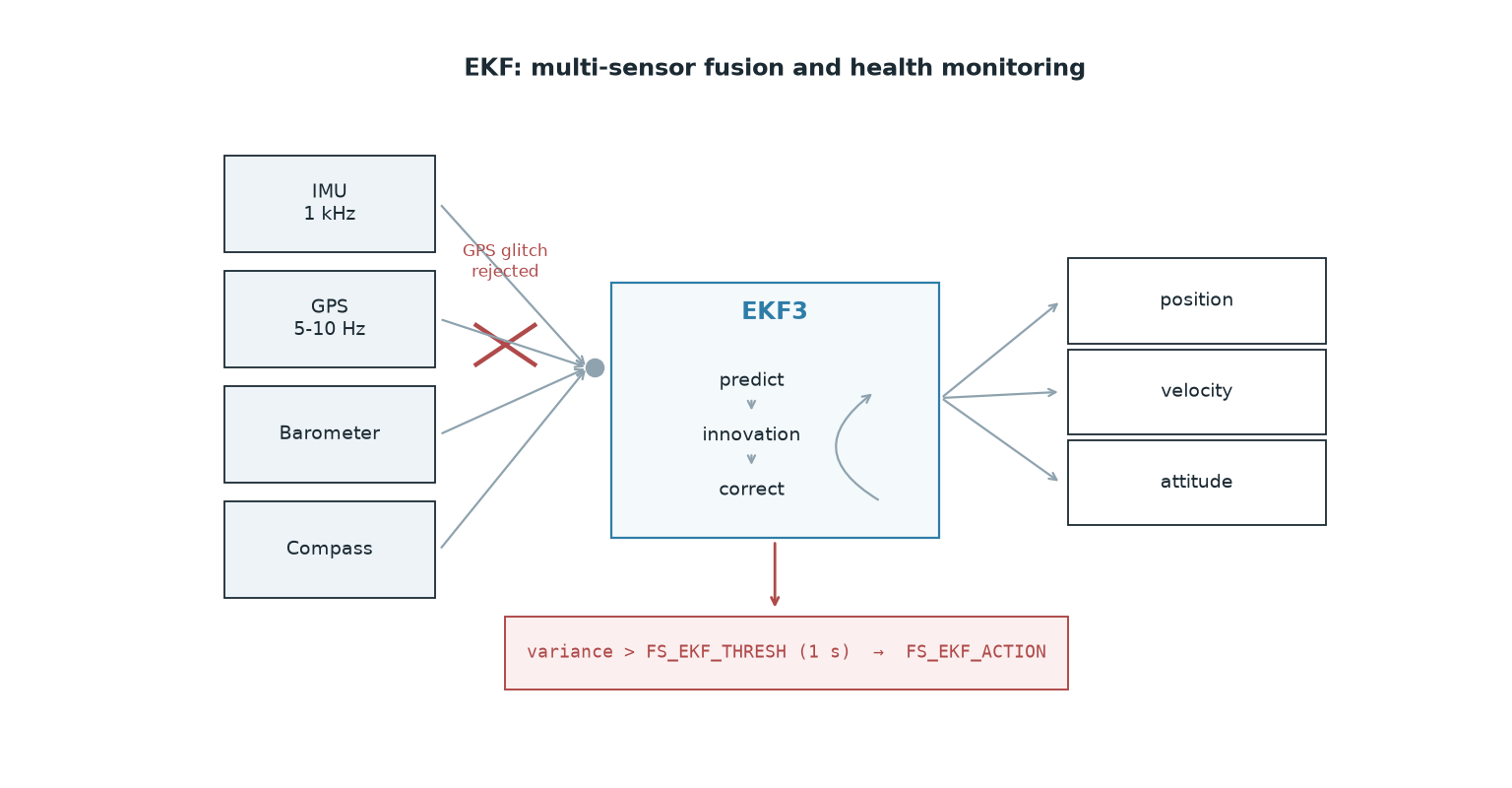
Even the best GPS produces data at 5–10 Hz, drops out under a tunnel or a bridge, and can jump suddenly. An IMU (inertial measurement unit), by contrast, delivers data at kilohertz rates, but its integration error accumulates over time. A barometer measures altitude quickly, and is affected by wind and cabin pressure. A compass gives heading, and is affected by current-carrying wiring.
The EKF fuses all of it. In ArduPilot's own description, the filter estimates position, velocity, and angular orientation from gyroscope, accelerometer, compass, GPS, airspeed, and barometric pressure measurements. The gain is not simply "averaging": the filter produces an expectation for every measurement, computes the difference against the measurement that actually arrives (the innovation), and rejects any measurement that deviates too far. In other words, it can screen out clearly bad measurements.
In EKF3, which sensor supplies which quantity is parameterized explicitly:
Parameter | Value | Meaning |
|---|---|---|
| 3 | Use EKF3 |
| 3 | Horizontal position: GPS |
| 3 | Horizontal velocity: GPS |
| 1 | Vertical position: barometer (default) |
| 3 | Vertical velocity: GPS |
| 1 | Heading: compass |
Three separate source sets (SRC1/SRC2/SRC3) can be defined, and you can switch between them with an RC auxiliary switch or a MAVLink command, a mechanism designed for moving between GPS-available and GPS-denied environments. On top of that, if there is more than one IMU, the EKF runs in parallel "lanes"; each core processes a different IMU, and whichever is healthiest by consistency is the one that drives the output.
EKF health warnings and failsafe
The EKF reports its own confidence as a variance value between 0 (trustworthy) and 1.0 (untrustworthy). On ArduPilot Copter, if any two of the compass, position, and velocity variances exceed FS_EKF_THRESH for 1 second, the EKF failsafe fires.
Parameter | What it means | Notes |
|---|---|---|
| Failsafe threshold | Raising it toward 0.8–1.0 reduces false triggers but allows the deviation to grow; lowering it toward 0.6 triggers earlier. 0 disables the failsafe |
| What happens when it fires | 0 = report only, 1 = Land (default), 2 = AltHold, 3 = Land even in Stabilize |
| Maximum radius between the GPS and the filter's estimate | If exceeded, the position/velocity states are reset to GPS. Increasing it ignores larger glitches, but lets IMU and compass errors accumulate further |
When it fires, "EKF variance" appears on the Mission Planner HUD, the board's LED flashes red-yellow or blue-yellow, and you get an audible warning. In the log, filter on ERR messages: code 16 is EKF Check (Bad Variance), code 17 is EKF Failsafe.
Safety note: blindly raising FS_EKF_THRESH, or setting it to 0, to get rid of a nuisance alarm means letting an aircraft with a broken position estimate keep flying in an autonomous mode; that is exactly the flyaway risk. Find the cause first. And try failsafe behavior first in a SITL/Gazebo environment, not in the field.
Common pitfalls
Putting the compass next to a power cable. The leads running to the ESCs carry tens of amps and generate a magnetic field proportional to that current. If your heading walks as you add throttle, this is the culprit. The fix: move the compass up onto the mast with the GPS module, run the power leads as a twisted pair, and keep them away from the compass. In the log, plot the tlog mag_field value against throttle command: the ArduPilot documentation gives a typical range of 120–550 (mostly around 330); fluctuation under 30% is acceptable, while jumps over 60% mean serious interference.
Calibrating on a metal bench. During compass calibration there should be no computer, phone, metal workbench, or power supply nearby, including the electronics in your pockets. If the calibration will not hold, COMPASS_OFFS_MAX (default 850) can be raised to 2000–3000, but that usually just hides the real problem.
Never looking at HDOP before flight. Passing the arming check does not mean the position is good. Wait for the satellite count and HDOP to settle before takeoff; the values keep improving over the first 30-60 seconds.
Mistaking RTK Float for Fixed. Seeing "RTK" on the ground station is not enough; fix_type has to be 6. Do not plan a precision drop on Float.
Failing to recognize vibration as a position problem. High vibration saturates the accelerometer, the EKF's vertical velocity and position estimates degrade, and you get "EKF variance" even when the GPS is flawless. Before you go hunting for glitches, look at the VIBE values in the log.
Being stuck with a single GPS. With two receivers you can use GPS_AUTO_SWITCH=1 (pick whichever reports the better accuracy) or =2 (blend the two). If compass interference is chronic, you can derive heading from GPS with a moving baseline setup: at least 30 cm between the two antennas, GPS_AUTO_CONFIG set appropriately, and EK3_SRC1_YAW=2 (GPS) or 3 (GPS with compass fallback).
Practical summary
Check three numbers before you fly: satellite count, HDOP (
GPS_HDOP_GOODdefaults to 1.4), andfix_type. Do not switch to an autonomous mode until all three have settled.Raise the antenna, get the compass away from current. The cheapest gain in position accuracy comes from mounting geometry; do this before you reach for RTK.
Choose RTK according to the target. Waypoint flight runs fine on standard GNSS; for work that needs centimeters (precision landing, dropping on a tight target), wait for RTK Fixed and keep the baseline short.
Set the EKF sources deliberately. Configure the
EK3_SRC1_*set for your mission scenario, and make sureAHRS_EKF_TYPE=3.Do not disable the failsafe; find the cause. An "EKF variance" warning usually points to vibration, compass interference, or multipath. Raising the threshold silences the symptom and grows the risk.