FIG. 01
RECORD DATA
Category
Avionics
DATE
Last season, on a test flight, the battery in our RC transmitter died out in the field. The aircraft was at 60 meters altitude, roughly 200 meters away from us. A second later it switched to RTL (Return To Launch), climbed, flew back, and landed. Nobody intervened, because there was nothing left to intervene in.
What worked that day was not luck. Two weeks earlier we had triggered the same scenario ten times in SITL (Software In The Loop, the flight software running as a simulation on a PC), re-set the RTL altitude against the tallest tree on the field, and confirmed that the home point locked in the right place. A failsafe does not exist the moment you configure it; it exists the moment you test it.
This post covers the failsafe types in ArduPilot Copter, the right response for each one, how to calculate your battery thresholds, and how to trigger all of it in SITL. The parameter names have been verified against the ArduPilot documentation; names do change between releases, so confirm them against the full parameter list in Mission Planner.
Failsafe types and their ArduPilot equivalents
In ArduPilot, a failsafe is not one master switch; it is a set of checks that run independently of each other. Each has its own trigger, its own timeout, and its own action parameter.
Failsafe | Trigger | Key parameters | Default timeout |
|---|---|---|---|
RC link loss | No pulses from the receiver / throttle channel dropping below the threshold |
| 1 s |
GCS / telemetry loss | MAVLink heartbeat stops |
| 5 s |
Low battery (voltage) | Voltage staying below the threshold |
| 10 s |
Low battery (capacity) | Consumed mAh passing the threshold |
| immediate |
EKF failure | Two of the compass / position / velocity variances exceeding the threshold |
| 1 s |
Geofence breach | Altitude / radius / polygon boundary exceeded |
| immediate |
Crash detection | More than 30° of deviation between the demanded and the actual lean angle, held for 2 s |
| 2 s |
One shared behavior matters a lot: once an RC, GCS, battery, or terrain-data failsafe has caused a mode change, the vehicle stays in that mode even after the problem clears. It will not go back to the previous mode unless the pilot switches it manually. That is why waving the transmitter around on the assumption that "the link is back, I have control again" gets you nowhere.
Which response is right, and when?
The failsafe actions all come from more or less the same pool. The difference is which one is less bad in a given situation.
Action | What it does | When to prefer it | Its risk |
|---|---|---|---|
Warn Only (0) | Warns, nothing more | Early-stage battery warning, with the pilot still in control | No automatic protection at all |
BRAKE / LOITER | Stops where it is and holds position | At the geofence boundary, where the pilot is expected to make the call | If the problem is permanent, the battery runs out |
LAND | Lands where it currently is | The only sensible option when position is not trustworthy (EKF, GPS) | It lands somewhere you do not know the location of |
RTL | Climbs to the configured altitude, flies a straight line home, lands | When position is healthy and the return path is clear | That straight line can run through an obstacle |
SmartRTL | Returns by retracing the path it flew out on | Flights through cluttered or wooded areas, or between buildings | Without a stored path it will not engage and falls back to RTL/LAND |
In practice, on our SUAS 2026 aircraft we use the SmartRTL-first, RTL-fallback options for both the RC and the GCS failsafe (FS_THR_ENABLE = 4, FS_GCS_ENABLE = 3). When the position solution degrades there is nothing to debate: the EKF failsafe is LAND, because sending a vehicle that does not trust its own position 300 meters downrange is far worse than a controlled landing.
Setting the battery thresholds
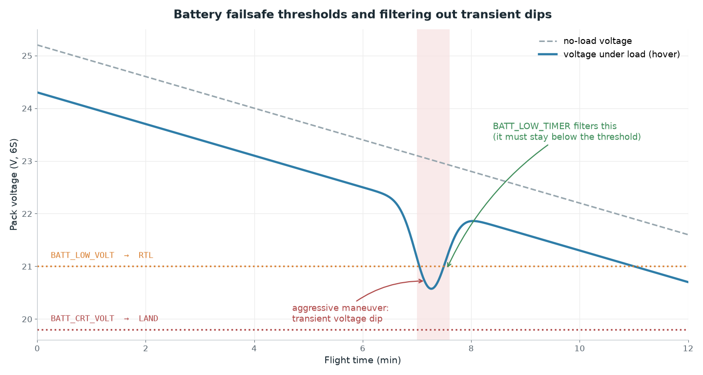
The most common mistake with the battery failsafe is setting the threshold from the resting (no-load) cell voltage. The moment the vehicle pulls current in a hover, internal resistance drags the voltage down; that is sag. Set the threshold against the no-load voltage and the failsafe will fire on the very first aggressive maneuver.
V_sag=I_hoverxR_internal, the voltage drop under load
V_threshold= (N_cellsxV_cell_target) -V_sag
Symbol | What it is, and where to get it |
|---|---|
| Hover current (A): the average of |
| Total internal resistance of the pack (ohm): from the |
| Cell count (6S -> 6) |
| The per-cell voltage you want to still see under load |
Example, a 6S pack, 22 A hover current, 0.020 ohm measured internal resistance, and we do not want to go below 3.5 V per cell under load:
V_sag= 22 A x 0.020 ohm = 0.44 VV_threshold= (6 x 3.5) - 0.44 = 21.0 - 0.44 = 20.56 V ->BATT_LOW_VOLT = 20.6Critical stage: (6 x 3.4) - 0.44 = 19.96 V ->
BATT_CRT_VOLT = 20.0
Two stages are mandatory. The low stage should send the aircraft home with BATT_FS_LOW_ACT = 2 (RTL), and the critical stage should put it on the ground wherever it happens to be with BATT_FS_CRT_ACT = 1 (LAND). Choosing RTL for the critical stage means attempting a 300-meter trip home on a pack that is already spent.
Voltage on its own is not enough. Set a capacity threshold alongside it: the ArduPilot documentation suggests roughly 20% of pack capacity for BATT_LOW_MAH (1000 mAh on a 5000 mAh pack). The capacity counter depends entirely on how well the current sensor is calibrated; with an uncalibrated sensor, an mAh threshold gives you no real confidence.
BATT_LOW_TIMER defaults to 10 seconds (0-120 s): the voltage has to stay below the threshold for that long, so momentary current spikes do not trip the failsafe. If you select BATT_FS_VOLTSRC = 1, ArduPilot uses the sag-compensated voltage, in which case you should pick a threshold closer to the no-load voltage.
Safety warning: Taking a LiPo cell below 3.0 V does permanent damage to the pack and increases the risk of swelling and thermal runaway. Do not drag the critical failsafe threshold down just to squeeze in one more lap. And do not run threshold tests on the ground with the props on: a full-throttle run with propellers fitted, purely to draw current, is a serious injury risk. Measure current and sag either with an electronic load or from a real flight log.
RTL altitude and the risks of the return path
RTL first climbs the vehicle to RTL_ALT_M (before Copter 4.6 the parameter is RTL_ALT and the unit is centimeters; check your version), then flies a straight line home. The default is 15 meters, and that is not enough on a site with trees or buildings.
RTL_ALT_M=tallest_obstacle_height+safety_margin
If the tallest obstacle on our field is an 18 m tree line, we set RTL_ALT_M = 28 with a 10 m safety margin. This altitude has to be re-set for the site before every competition and every flight; "it worked last time" is not a justification.
Here is the critical part: RTL returns in a straight line, it does not retrace the path you flew. If you flew out from behind a building, RTL will try to take you straight through it. That is why we run SmartRTL-first options on cluttered sites. RTL_CONE_SLOPE (default 3) limits pointless climbing near home; if the failsafe fires directly above home, the vehicle rises along a short cone instead of going all the way up to 28 meters.
If RTL_ALT_FINAL_M is left at zero, the vehicle lands automatically at the end of the return. Give it a non-zero value and it will hold at that altitude and wait for pilot input, and if the link is already gone, that means hanging in the air until the battery dies. Leave it at zero for the RC failsafe case.
Injecting failsafe scenarios in SITL
Do not try any of this for the first time in the field. In the environment from our SITL + Gazebo setup post, you can trigger the failsafes directly from the MAVProxy console:
For every scenario, answer a single question: what did the vehicle do, how long did it take to do it, and what message showed up in the log? Speeding things up with SIM_SPEEDUP lets you run ten scenarios during a coffee break, but at very high values the simulation itself can manufacture failsafes, so verify your results at 1x.
Common pitfalls
An untested failsafe. Typing in the parameter and closing Mission Planner is not a test. Trigger it at least once in SITL and once in the field under controlled conditions: high altitude, open area, transmitter switched off.
The wrong home point. Home is normally locked in at the moment of arming. Arm with a weak GPS fix and home can end up hundreds of meters away, and RTL will happily take you there. Check HDOP and satellite count before arming, and look at Mission Planner to confirm the home icon really is at your feet.
Too low an RTL altitude. Flying a tree-lined site at the default 15 m turns your failsafe into a collision procedure.
Choosing RTL for the critical stage. If the voltage has reached the critical threshold, there is no energy left for the trip home. The critical stage has to be LAND.
Thresholds based on no-load voltage. A threshold set without doing the sag math either fires early or never fires at all.
Assuming the failsafe will undo itself. Even when the link comes back, the vehicle stays in the failsafe mode; the pilot has to change modes manually.
The companion computer overriding the failsafe. If you are sending commands over MAVLink from the Jetson, a script that keeps pushing setpoints in GUIDED mode can fight the mode change that follows a failsafe. When a failsafe fires, offboard control has to go quiet.
Practical summary
Enable all six failsafes (RC, GCS, battery, EKF, geofence, crash) one at a time; do not leave any of them at their defaults.
Calculate the battery threshold with
V_threshold = (N_cells x V_cell_target) - I_hover x R_internal; set up two stages (low -> RTL, critical -> LAND).Set
RTL_ALT_Mbefore every flight by adding a safety margin to the tallest obstacle on the site, and leaveRTL_ALT_FINAL_Mat zero.Whenever position reliability is in doubt (EKF, GPS), the action should always be LAND; on a cluttered site, prioritize SmartRTL over RTL.
Inject every scenario in SITL before you fly, using
SIM_RC_FAIL,SIM_BATT_VOLTAGE,SIM_GPS1_ENABLE, andSIM_ENGINE_FAIL; verify the response and its timing from the log.Before arming, visually confirm that the home point really is in the right place.