Airframe & Structural Design
AUAV-AFR-2026-01
The Atılım UAV airframe is a foldable quadcopter structure built around a two-plate G10 composite central fuselage carrying 20 mm carbon fiber arms. Strategic cutouts patterned into the top and bottom chassis plates achieve weight reduction and simplify internal wire management, and structural spacers integrated between the plates increase bending stiffness and help the two plates act as one structural assembly. G10 was selected because it offers high in-plane stiffness and excellent electrical insulation while remaining RF-transparent, which prevents a Faraday cage effect around the internal telemetry, RC, and GNSS receivers. The arms attach through foldable joints that lock securely in flight and fold inward for transport, the landing gear uses a telescopic leg mounted on a pivot with a spring-assisted mechanism that holds it in either position, and the battery pack is secured with hook-and-loop fasteners instead of permanent fixtures — together these let the aircraft deploy without tools. The motor mounts are manufactured in house from wrought 6061-T6 aluminum and fit the 20 mm carbon fiber tubes, transferring motor thrust and torque into the primary structure. In flight configuration the aircraft measures 21.2 x 21.2 x 11 inches; folded for transport it collapses to 13 x 13 x 7.1 inches, which fits within the 18 x 14 x 8 inch “Personal Item” sizing tier.
PDF · 8 pagesDownload
1 Airframe Configuration
The aircraft is a folding multirotor. A flat central fuselage — two profiled G10 fiberglass plates separated by spacers — sits at the middle, and the main carbon fiber arms run out from it. Each arm carries an aluminum motor mount and a telescopic landing leg on a foldable joint. Figure 1 shows the aircraft in its deployed flight configuration.
Six requirements shaped the structure, and every part described in this document answers at least one of them:
Weight reduction, and internal wire management that does not fight the structure.
RF transparency around the internal telemetry, RC, and GNSS receivers.
A stiff primary load path from the motor mounts to the main plates.
Tool-less assembly, so the aircraft can be deployed and serviced rapidly in the field.
Foldable landing gear that stays stable in both its deployed and folded positions.
A transport envelope that fits the 18 x 14 x 8 inch “Personal Item” sizing tier.
This modular arrangement means damaged arms, landing-gear components, and other critical parts can be replaced without dismantling the complete airframe.
Sections 2 to 4 follow the structure outward from the fuselage to the arms and the manufactured parts; Section 5 covers the structural simulation and fatigue assessment, and Section 6 covers the folded transport configuration. Table 1 collects the material choices in one place, with the property each part was selected for.
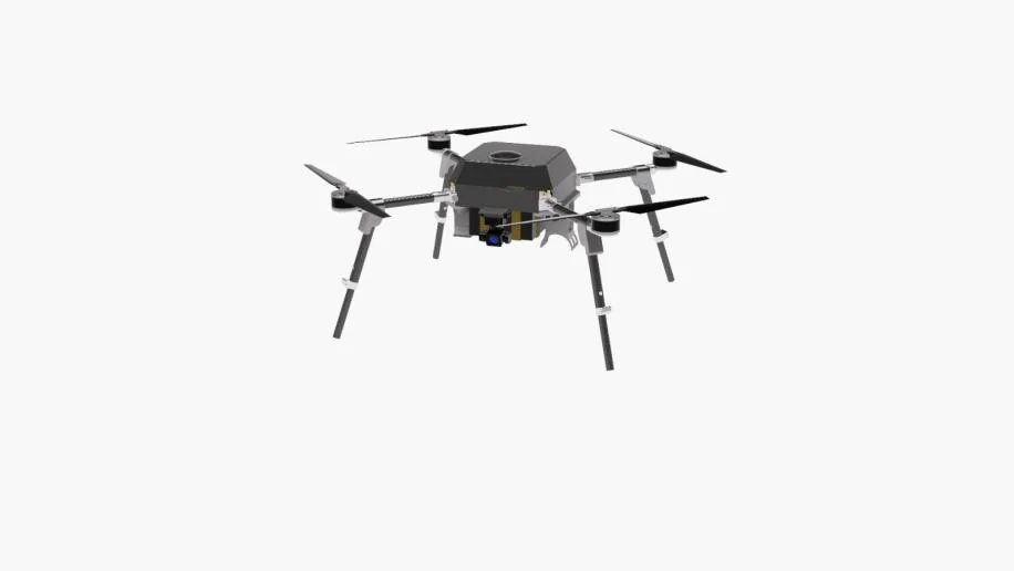
Figure 1. The airframe in its deployed flight configuration, from the CAD model. What to read from it is the geometry the folding architecture has to produce on demand: arms out to full span, telescopic legs extended below. The central body is enclosed by a canopy here, so the plate stack described in Section 2 is not visible in this view.
2 Central Fuselage
The central fuselage is constructed entirely from G10 fiberglass laminate. Structurally it is a stack: a top and a bottom profiled plate held apart by spacers, with every other structural member on the aircraft terminating there. What defines it is the cutout pattern in the plates, the choice of G10, and the spacers that tie the two plates into one box.
2.1 Plate Geometry and Mass Reduction
Strategic cutouts were patterned into both the top and the bottom chassis plate. The pattern does two jobs at once: it removes laminate to bring plate mass down, and it simplifies internal wire management, so harnesses pass through the structure instead of around it. Figure 2 shows the two plate profiles.
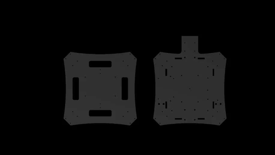
Figure 2. The top and bottom chassis plate profiles, from the CAD model. What to look at is how much laminate the slot pattern removes, and that the two plates are not identical.
2.2 Why G10
G10 was specifically selected because it provides high in-plane stiffness and excellent electrical insulation while remaining RF-transparent. All three properties were required. The RF transparency is the one that concerns the avionics: a conductive shell would produce a Faraday cage effect around the internal telemetry, RC, and GNSS receivers, whereas the fiberglass laminate lets those signals pass through with negligible attenuation and is suitable for mounting antennas and wireless components inside the airframe.
2.3 Spacer Columns and Structural Rigidity
Spacers installed between the two main plates increase bending stiffness and help the two plates act as one structural assembly, acting as rigid, load-bearing internal beams. Figure 3 shows the assembled stack, with the harness running through the gap the spacers open.
The specific spacer count is not stated in the source design documentation. The structural analysis reported in Section 5 covers the foldable arm and motor mounts; no separate analysis, load case, or test result for the plate stack itself is reported in this document.
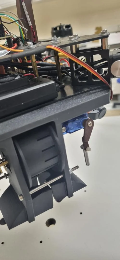
Figure 3. The assembled plate stack, photographed from the side. The spacers standing between the two plates are the load-bearing members described here, and the wiring runs through the gap they open. The photograph also shows a servo and a mechanism below the lower plate that this document does not describe.
3 Folding Architecture and Tool-Less Assembly
Designed for immediate rapid response, the aircraft has a complete tool-less folding topology: every joint that changes between transport and flight moves by hand, with nothing to unbolt. Figure 1 and Figure 5 are the two ends of that motion, the same aircraft deployed and folded.
3.1 Arms and Foldable Joints
The main carbon fiber arms attach through foldable joints that lock securely in flight position and fold inward for transport, selected for quick deployment. Section 4 covers the motor mounts manufactured in house for these arms.
3.2 Landing Gear and Battery Mounting
The landing gear takes its inspiration from a folding motorcycle side stand. Each telescopic leg is mounted on a pivot near the motor mount, with a spring-assisted mechanism that helps hold the gear in either its deployed or its folded position; Figure 1 shows the legs extended, Figure 5 the same legs collapsed. The battery pack is secured with hook-and-loop fasteners instead of permanent fixtures, allowing rapid battery replacement in the field.
4 Manufacturing and Motor Mounts
The motor mounts are the airframe’s critical load-transfer components, engineered and manufactured entirely in house.
Each motor mount is manufactured in house from wrought 6061-T6 aluminum. The mounts are specially designed for the team’s propulsion system and fit the 20 mm carbon fiber tubes, so motor thrust and torque transfer into the primary structure through that joint. Figure 4 shows the mount geometry.
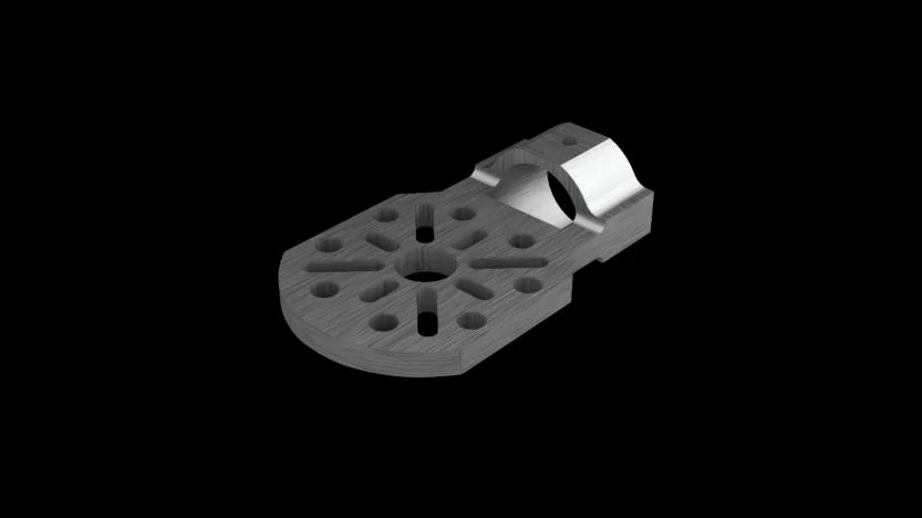
Figure 4. The in-house motor mount, shown as a CAD model. The bolt pattern and the lightening holes sit on the circular face; the semicircular saddle on the right is the fitting interface to the 20 mm carbon fiber tube.
Table 1 sets the material choices out in full, one row per part, alongside the property each was selected for.
Table 1. Airframe materials and the property each part was selected for.
Item | Material or part | Property it was selected for |
|---|---|---|
Top and bottom chassis plates | G10 fiberglass laminate | Strength-to-weight ratio; RF-transparent, which prevents a Faraday cage effect around the internal telemetry and GNSS receivers |
Inter-plate spacers | Structural spacers | Increase bending stiffness; help the two plates act as one structural assembly |
Main arms | Carbon fiber; 20 mm tubes | Low-mass primary load path; 20 mm is the tube size both the arm joints and the motor mounts are made to fit |
Arm joints | Foldable locking joints | Tool-free deployment; individual arm replacement |
Motor mounts | Wrought 6061-T6 aluminum, machined in house | Fits the 20 mm carbon fiber tubes; transfers motor thrust and torque into the primary structure |
Leg-to-arm pivot joints | Pivoted joint near the motor mount | Lets the leg fold with the spring-assisted mechanism |
Landing legs | Telescopic, pivoted, spring-assisted mechanism | Stable in both deployed and folded positions |
Battery mounting | Hook-and-loop fasteners | Rapid replacement; no permanent fixtures |
5 Structural Simulation and Fatigue Assessment
To validate the structural integrity of the foldable arm and motor mounts under operating loads, these components were analyzed in ANSYS under the thrust loading generated during flight. Static analysis confirmed that the foldable arm and motor mounts maintain a safety factor of 1.5 against yield under maximum thrust load. Repeated stress from motor operation and from folding and unfolding cycles was also considered, to assess durability over repeated competition use.
Table 2 summarizes the resulting vehicle mass and performance figures.
Table 2. Vehicle mass and performance summary.
Metric | Value |
|---|---|
Dry weight (no payload) | 5.9 kg |
Operational weight (both payloads) | 6.7 kg |
Maximum takeoff weight | 11 kg |
Maximum horizontal speed | 18 m/s |
Maximum vertical speed | 5 m/s |
Flight endurance (operational weight) | ~30 min |
Maximum flight range | 32 km |
6 Transport Configuration and Portability
The folding architecture exists for this result. The foldable arm joints and the telescopic legs together allow this autonomous platform to collapse into a compact footprint: in flight configuration the aircraft measures 21.2 x 21.2 x 11 inches, and folded for transport it measures 13 x 13 x 7.1 inches, which fits within the 18 x 14 x 8 inch “Personal Item” sizing tier. That is the logistical argument for the whole folding design. Using hands only, the aircraft can be unpacked and prepared for flight in approximately three minutes.
Deployed, the same airframe opens to a wide and stable aerodynamic stance. Figure 5 shows the folded transport mode; set against Figure 1 it gives the honest measure of what the joints and the telescopic legs are doing, since the two figures are the same aircraft.

Figure 5. The aircraft folded for transport, from the CAD model. The arms have swung back alongside the body and the legs have collapsed against it; this is the 13 x 13 x 7.1 inch configuration referred to in the text.