FIG. 01
RECORD DATA
Category
Project Diary
DATE
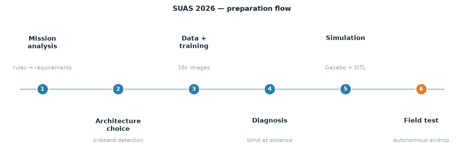
From the outside, preparing for a competition looks like "building a drone." From the inside it is something else entirely: turning the rulebook into engineering requirements, then verifying those requirements one at a time. In this post we walk through our whole SUAS 2026 preparation, start to finish: the parts that worked, and just as much, the places we tripped.
What does the mission ask for?
SUAS (Student Unmanned Aerial Systems) is an international competition in which teams build autonomous unmanned aircraft systems. The headline mission of the 2026 season is "Search, Detect, and Deliver":
Inside the search boundary there is one mannequin and one pop-up tent.
Find the mannequin and you drop a water bottle; find the tent and you drop a strobe beacon.
The targets are scattered among debris and can be partially occluded.
The release has to happen from an altitude of at least 150 ft (roughly 46 m).
On top of that there is the Risk Mapping task: a stitched image map of the roughly 10-acre search area, delivered within the mission window.
The most useful thing we did in our first working session was to read these items not as a to-do list but as a scoresheet. Which task is worth how many points, what does each penalty cost us, and which tasks can share a single flight? The answers shaped the design directly.
One flight, three missions
This was our earliest strategic decision: no separate mapping flight.
During the waypoint lap planned in Mission Planner, the aircraft does two jobs at once: it collects the mapping imagery and runs the onboard detection pipeline, logging the position of every target it finds. Image capture ends at the final waypoint. The aircraft then flies to the logged positions, centers itself over the object, and releases its payload.
So a single search pass feeds the waypoint score, the mapping score, and the detection phase all at once. With the mission window capped at 45 minutes, that is not a paper "optimization"; it is points on the board.
System architecture
Three pieces, roughly:
Layer | What is in it | What it does |
|---|---|---|
Flight | Pixhawk-class flight controller + ArduPilot | Navigation, failsafe, AUTO mode |
Perception | SIYI A8 mini gimbal camera + Jetson Orin NX | Video stream, object detection, position logging |
Ground | Mission Planner + telemetry link | Mission planning, monitoring, map delivery |
The camera feed arrives at the Jetson as an RTSP stream, and detection runs entirely onboard the aircraft. That was a deliberate call: moving detection to the ground station would make video link quality mission-critical. We did not want the aircraft going blind the moment the link drops.
Where we tripped
It would have been easy to tell this story as "everything went according to plan," but the instructive part is exactly the opposite. We hit two big walls:
1. The model could not see at range. The first model we trained found nearby targets with high confidence, and then produced no detections at all once the distance opened up a little. There was no falloff in between: either it saw the target clearly or it saw nothing. Digging out the root cause turned into a much more instructive excavation than we expected (separate post: "Sharp Up Close, Blind at Range").
2. The correct fix would not run in real time. Sliced inference (tiling), the known answer to the small-object problem, genuinely rescued our detection capability, but on the Jetson it dropped us to 1-3 frames per second. Far too slow for closed-loop guidance. The measurement forced us to change the design (separate post: "Tiling or Frame Rate?").
In both cases, what moved us forward was measurement, not guesswork.
Flying before we flew: simulation
Before heading to the field we built a simulation environment tying together Gazebo, ArduPilot SITL, ROS 2 and pymavlink. The real trick here was this: we built it distributed. The flight dynamics simulation, the ground station and the actual Jetson each ran as separate nodes on the network, with the camera feed again reaching the Jetson over RTSP.
The upshot is that the hardware and network topology we would use in the field had been exercised one-for-one before the first flight ever happened. We also triggered failure scenarios here (GPS/EKF degradation, link loss, low battery) and verified the failsafe behavior against the telemetry logs.
The real value of simulation fits in one sentence: field flights are for confirming behavior, not discovering it.
The first autonomous airdrop
In our first comprehensive field test, the system did the following:
Detected both targets from roughly 20 m altitude
Handed the detected positions off to guidance
Flew to the release points autonomously
The beacon landed squarely on the tent
The water bottle landed within about 5 m of the mannequin
In a separate test we also detected human stand-ins on concrete after dark under dim artificial light, from 20-25 m, across 6 runs, at roughly 0.75 confidence. That one mattered to us: there is no guarantee that the light on competition day will resemble our training data.
Let us be blunt that this was a single test. One flight is not enough to say "the system works"; it is enough to say "the system can work." Statistics need repetition.
What is next
When this record was written our biggest gap was obvious: verified detection altitude ~20 m against a release floor of ~46 m, with no attempt yet in that band. That gap has since been closed, and what closed it was optics rather than a bigger network. Detection is now flown with 3x digital zoom — the 4K sensor read cropped down to a 31.8° field of view — so at 50 m the ground sample distance is 14.8 mm/px instead of 44.5, and a 1.7 m mannequin spans roughly 38 px in the 640 px inference input. That is close to the ~32 px we had at 20 m at unity zoom: the zoom pays back what the altitude costs.
What we have measured since: at 49 m AGL with the camera at 3x, a human stand-in was detected at 0.60-0.80 confidence, comfortably above our 0.25 operating threshold. We then repeated the whole end-to-end chain at the 50 m mission altitude: similar detection confidence, delivery error of the same order as the low-altitude run, and both payloads inside the 50 ft (15.2 m) scoring radius. The flight configuration is full-frame 640 px inference at a 0.25 threshold — deliberately low, because the release decision keys on continuity rather than on any single frame, requiring the target to hold within 20 px of frame centre across consecutive frames. Sliced inference with TensorRT stays on the shelf as a fallback; it never met the frame rate autonomous guidance needs, so it is not the flight configuration.
What is left:
Closed-loop verification of the terminal guidance loop on live imagery — the field releases so far were commanded from logged geolocation
Measuring drop accuracy repeatedly and turning it into a distribution
Camera calibration
We will share every one of these steps in this blog series, whatever the outcome. Writing about the parts that work is easy; the genuinely useful part is how the part that does not work gets diagnosed.
This post is part of a series: in the following posts we go into the root-cause analysis of the detection failure, how we merged our datasets, and the speed/accuracy trade-off on the Jetson in detail.
NEIGHBOURS