FIG. 01
RECORD DATA
Category
Avionics
DATE
The scenario we hit most often in the field goes like this: we plan the mission at home in the evening, write it to the aircraft in the morning, switch to AUTO, and the aircraft flies 20 meters lower than we planned. Nobody did anything wrong. The altitude frame was set to "Relative" while the home point had been set at a different elevation than the spot we actually took off from.
Dropping waypoints on a map is easy; making a mission behave the same way on four different sites with four different home points takes discipline. This post walks through the workflow we use while preparing for SUAS 2026: the anatomy of the screen, picking commands, generating a survey plan with Survey/Grid, writing the mission to the aircraft, and the preconditions for switching into AUTO.
The parameter names are for ArduPilot Copter. With Copter-4.7.0 many of them were converted to SI units and renamed (WPNAV_SPEED → WP_SPD, RTL_ALT → RTL_ALT_M, and so on); if you are on older firmware, use the names given in parentheses.
Anatomy of the Flight Plan screen
The map sits at the top of the screen with the mission table underneath it; every row in that table is one command. The Default Alt field sets the default altitude for newly added waypoints. Clicking on the map appends a new NAV_WAYPOINT row carrying that point's latitude and longitude.
The right-click menu is where the real work happens: Draw Polygon → Add Polygon Point traces the boundary of the survey area, Auto WP → Survey (Grid) turns that polygon into an automatic survey mission, and Prefetch downloads the map tiles for the site ahead of time (there may be no internet at the field; we do this every single time).
The four buttons along the bottom decide the life cycle of a mission:
Button | What it does | When |
|---|---|---|
Write | Sends the mission to the autopilot and writes it to EEPROM | Once the plan is finished |
Read | Reads the mission back off the aircraft | Immediately after Write, to verify |
Save WP File | Saves it to disk as a | Version tracking, backup |
Load WP File | Loads a saved mission | Fast recovery in the field |
The Verify height checkbox uses Google Earth elevation data to correct each waypoint's altitude against the ground elevation beneath it. Useful if you are working on sloped terrain, but it is not terrain following on its own; it is only a correction applied at planning time.
Altitude frame: half the mistakes start here
Every waypoint has an altitude frame, and confusing those frames is the most expensive mistake there is. Three options:
Frame | Zero reference | When to use it | Risk |
|---|---|---|---|
Relative | Elevation of the home point | Default choice on flat sites; most competition missions | If home is set wrong, the whole mission shifts vertically |
Absolute | Mean sea level (AMSL) | When you were handed a ceiling in AMSL (NOTAM, ATC restriction) | Barometer/GPS elevation error feeds straight into altitude |
Terrain | The ground itself | Sloped or hilly terrain, surveys that need a constant height above ground |
|
If you are going to use Terrain, two things have to be true: TERRAIN_ENABLE = 1, and the ground control station must have pushed SRTM data to the aircraft over MAVLink (Mission Planner, QGroundControl and MAVProxy all support this). The ArduPilot documentation puts SRTM accuracy on the order of 10 meters on average, varying by region, and recommends terrain following for altitudes above 60 m; lower than that, rangefinder-based following gives more accurate results.
Our practical rule: do not mix frames inside a single mission file.
The command set: which row we add and why
Command | Key fields | When we reach for it |
|---|---|---|
| Alt | First NAV command of the mission. If the aircraft is already above that altitude, the command counts as complete and it moves on to the next waypoint |
| Delay, Hit Rad, Yaw Ang, Lat/Lon/Alt | The workhorse. With Delay > 0 it holds over the point |
| Time (s) / Turns, Radius | An observation pause, or orbiting a target to collect imagery |
| Lat/Lon/Alt | Smooth turns without bleeding speed; shortens the time on survey lines |
| Lat/Lon/Alt | Locking the nose/gimbal onto a fixed target |
| Type, Speed (m/s) | Slowing down on a survey line, speeding up in transit |
| Ser No, PWM (1000–2000) | Releasing the airdrop latch |
| Distance (m) | Distance-based camera triggering (the Survey tool computes this itself) |
| WP no, repeat count | Flying the same lap N times |
| None | Climbs to |
| Lat/Lon | Landing at a specific point |
At most one "Navigation" command and one "Do" command run at the same time during a mission; Do commands are processed after the navigation command ahead of them finishes. That is why DO_SET_SERVO cannot be the first or last command in a mission. The second detail that burned us for a day on the airdrop side: for the command to fire at all, the SERVOn_FUNCTION value of that output must be 0 (Disabled); if the function is assigned to something else, the command is silently ignored.
Our servo-based airdrop releases were done from roughly 20 m; we put DO_SET_SERVO on the row right after the NAV_WAYPOINT that immediately precedes the release point.
Safety: run servo/airdrop tests with the propellers removed. Pixhawk-class autopilots cannot power a servo directly; you need an external 5V BEC. Exercising the servo command without arming is the cheapest way to validate the trigger logic.
Survey/Grid: set line spacing with a formula, not a guess
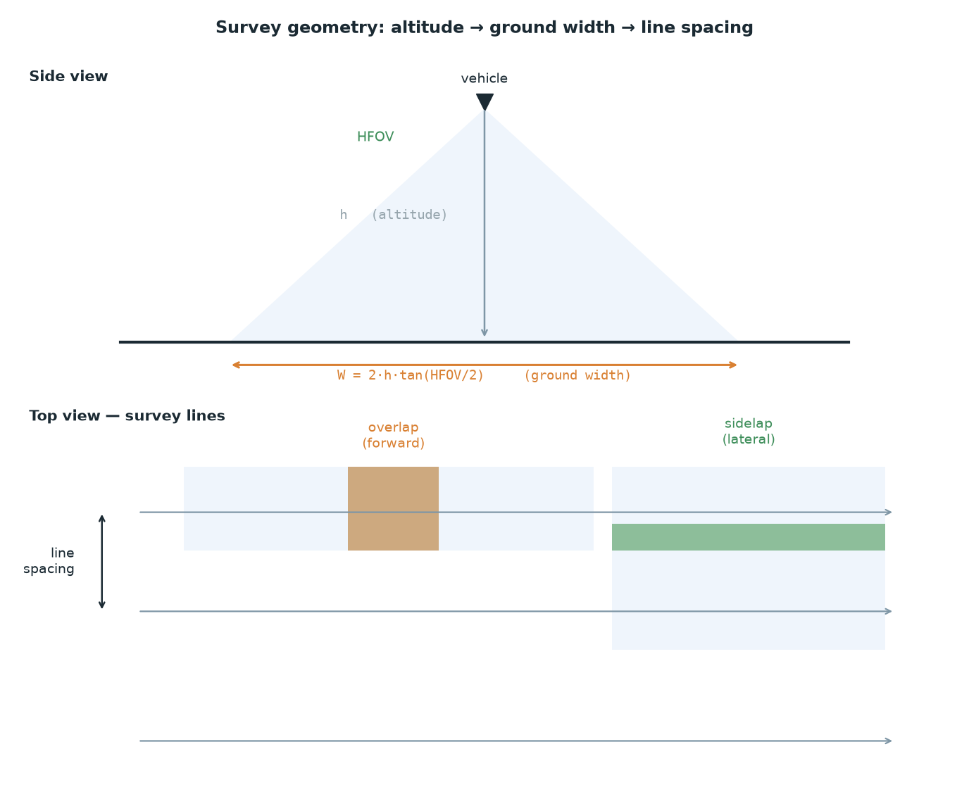
Once you have drawn the polygon and chosen Auto WP → Survey (Grid), Mission Planner asks for the camera model plus the overlap (forward) and sidelap (lateral) values; opening the advanced options exposes the lens and sensor fields. From those inputs it computes the DO_SET_CAM_TRIGG_DIST spacing itself and appends a command at the end of the mission that resets the value to zero. The field names move around between MP versions, but the math behind them does not:
Ground footprint (pinhole approximation, lens distortion ignored)
width_m= 2 *altitude_m* tan(HFOV / 2)
height_m= 2 *altitude_m* tan(VFOV / 2)Derive VFOV from HFOV for a 16:9 frame
tan(VFOV/2) = tan(HFOV/2) * (9 / 16)
Planning outputs
line_spacing_m=width_m* (1 - sidelap)
trigger_distance_m=height_m* (1 - overlap), which isDO_SET_CAM_TRIGG_DIST
GSD_cm_px= (width_m* 100) /image_width_px
Worked through step by step for our own setup (SIYI A8 mini, 81° HFOV, 1080p) at 40 m:
tan(81/2) = tan(40.5°) = 0.854
width = 2 * 40 * 0.854 = 68.3 m
tan(VFOV/2) = 0.854 * 0.5625 = 0.480 -> VFOV = 51.3°
height = 2 * 40 * 0.480 = 38.4 m
60% sidelap -> line_spacing = 68.3 * 0.40 = 27.3 m
75% overlap -> trigger_distance = 38.4 * 0.25 = 9.6 m
GSD = 6830 cm / 1920 px = 3.6 cm/px
Survey a 300 × 200 m area with 300 m lines and you get: 200 / 27.3 = 7.3 → 8 lines. Total path ≈ 8×300 + 7×27.3 = 2591 m. At WP_SPD = 8 m/s that is ≈ 324 s, or roughly 6-7 minutes once you account for slowing down in the turns. If it does not fit into a single flight, splitting the area in two is a better idea than climbing higher, because GSD feeds directly into detection: at 3.6 cm/px a 30 cm target is about 8 pixels, and that is borderline for raw inference. The details are in our post on small object detection and SAHI sliced inference.
Writing the mission and switching to AUTO
The preconditions we check before pressing Write:
A 3D GPS fix and a sane HDOP. The ArduPilot documentation uses an HDOP below 1.4 as the reference for AUTO.
The home point has to be set. Home is written to wherever the aircraft is at the moment of arming. If you moved it by hand from the GCS with "Set Home Here", RTL will return to that point.
Arm. With default settings you cannot arm in AUTO; you arm in another mode (Loiter, for example) and then switch to AUTO. The
AUTO_OPTIONSparameter can change this behavior.If you are starting from the ground, the throttle stick has to be down; after switching to AUTO, the mission starts the moment you bring the throttle above zero. If you are already airborne, it starts from the first command the instant you switch to AUTO.
Re-entering AUTO resumes the mission from the last command; set
MIS_RESTART = 1to make it start over from the top.
In simulation (see our SITL + Gazebo guide) we verify these preconditions with a script instead of clicking through them by hand:
If you are building out the MAVLink side through a companion computer, our MAVLink guide picks up where this flow leaves off.
Geofence and RTL altitude
Do not think about the geofence separately from the mission: if the two sets of numbers contradict each other, the aircraft changes mode mid-mission. It is turned on with FENCE_ENABLE = 1; FENCE_TYPE is a bitmask (bit 0: maximum altitude, bit 1: a cylindrical "tin can" around home, bit 2: polygon, bit 3: minimum altitude). FENCE_RADIUS must be at least 30 m and must stay larger than FENCE_MARGIN. What happens on a breach is decided by FENCE_ACTION (RTL, LAND, BRAKE and so on).
RTL_ALT_M (formerly RTL_ALT, in cm) is the minimum altitude the aircraft climbs to before heading home; per the ArduPilot documentation the default is 15 m, and a value of 0 makes it return at its current altitude. With RTL_ALT_TYPE = 1 that altitude is interpreted as height above ground. The check is simple: RTL_ALT_M < FENCE_ALT_MAX − FENCE_MARGIN, and keep your highest waypoint below that ceiling as well.
Common traps
The wrong altitude frame. If the elevation of the site differs from the elevation of the map you drew the plan on, a Relative mission shifts wholesale. When you arrive at the site, re-set home and make one pass with Verify Height.
The home point surprise. Home is written at the moment of arming. If you move the aircraft and take off from a different spot, the distances in the old mission file are still right but the altitude reference is wrong.
Enlarging the WP radius.
WP_RADIUS_M(formerlyWPNAV_RADIUS, in cm; default 2 m) is the radius within which a waypoint counts as "reached". Increase it and the aircraft cuts corners and can miss the airdrop point by meters; decrease it and you get stop-and-go behavior and a longer flight time.Putting
DO_SET_SERVOon the first or last row, or not leavingSERVOn_FUNCTIONat 0.Choosing Terrain but leaving
TERRAIN_ENABLE = 0. The mission writes fine, but altitudes are not interpreted the way you expect.Not doing a Read after Write. On a weak telemetry link the mission can be written incompletely; Read is a 5-second insurance policy.
Practical summary
Pick the frame once and do not change it for the rest of the mission. Relative on flat sites, Terrain on sloped ground (plus
TERRAIN_ENABLE = 1and downloaded SRTM data).Set survey altitude from the GSD math, not from "let's fly high and fit it all in". Run the formula once with your own camera's HFOV and write the answer down.
Follow every Write with a Read and keep the mission as a versioned
.waypointsfile.Four checks before AUTO: 3D fix, home correct, armed in another mode, throttle down. Read these off a checklist in the field, not from memory.
Validate the fence and RTL numbers together with the mission:
RTL_ALT_M<FENCE_ALT_MAX−FENCE_MARGIN, and the highest waypoint below that ceiling.
We do not take this flow to the field without flying it in SITL at least once; a frame error caught in 10 minutes of simulation costs half a day at the site.