FIG. 01
RECORD DATA
Category
Mechanics
DATE
On our first autonomous drop in the field, everything went exactly the way we planned it: the aircraft flew to the target's GPS coordinate, the servo fired, the latch opened, the water bottle dropped. Then, while hunting for the bottle on the ground, we found it sitting well past the target marker. The mechanism had worked flawlessly; the fault was not in the mechanism.
At first glance airdrop looks like a mechanical problem: "build a latch that holds the payload, open it on command." In practice it is the sum of three separate problems: a mechanism that holds the payload securely for the whole flight, a control chain that fires that mechanism at the right instant, and a ballistics calculation that predicts where the payload goes once it is released. Miss any one of the three and the system "works" but doesn't hit anything.
In this post we go through all four in order: the mechanism options and how they compare, the servo torque calculation, the triggering methods available on the ArduPilot side, and the part that gets ignored most often (the physics of the drop itself). Every numeric example comes with the formula behind it so you can apply it to your own aircraft.
Mechanism options
There are four main approaches. Each of them has a scenario where it works well and a scenario where it falls apart.
Mechanism | How it works | Pros | Cons | When to choose it |
|---|---|---|---|---|
Servo latch | A servo pulls a pin or a latch and the payload free-falls | Simple, light, cheap, fast (0.1–0.3 s) | The payload free-falls; not suitable for fragile payloads or a gentle landing | Rugged payload, low altitude, missions where speed comes first |
Winch / cable lowering | A motorized spool pays out cable and the payload descends slowly | Soft landing, handles fragile payloads, precise placement from high altitude | Heavy, complex, slow (tens of seconds), risk of cable tangling | Fragile payload, terrain you can't land on, a loose time budget |
Electromagnet / EPM | Magnetic hold, released on command | No moving parts, no wear; an EPM draws no continuous current | The payload needs a ferromagnetic interface plate; risk of magnetic interference with the compass | Repeated pick-and-place missions, cases where mechanical wear is the problem |
Parachute | The payload is released and a parachute deploys | Low impact energy, protects a fragile payload | Wind drift grows dramatically and accuracy degrades badly | When landing the payload intact matters more than hitting the mark |
We went with a servo latch on our SUAS 2026 aircraft: the payload is rugged, mission time is tight, and the mass budget for the mechanism is narrow. A winch is the best option for accuracy because it removes the ballistics problem entirely, but the ~1 kg of extra mass and the 20–40 second release cycle did not fit our mission profile.
Two warnings on the electromagnet option. A conventional electromagnet draws current the entire time it holds (lose power and you lose the payload), while an electropermanent magnet (EPM, a magnet that only spends energy when it changes state) draws nothing at rest but pulls a brief high current at the moment of switching, and the manufacturer recommends a separate supply for it. In both cases, mount the magnet as far from the compass as you can and redo the compass calibration after installation.
Choosing a servo: the torque calculation
Servo torque is usually quoted in kgf·cm. The conversion:
1 kgf·cm = 0.0981 N·m
1 N·m = 10.2 kgf·cm
Scenario A: the arm carries the payload directly. The worst design, and also the most common one: the weight of the payload lands on the servo horn at a lever arm.
T = n × m × g × r
Symbol | Meaning |
|---|---|
| dynamic load factor (covers maneuvering and landing shock) |
| payload mass [kg] |
| 9.81 m/s² |
| perpendicular distance from the force to the servo shaft [m] |
Example:
m= 1.0 kg,r= 3 cm = 0.03 m,n= 1 (static)
T = 1 × 1.0 × 9.81 × 0.03 = 0.294 N·m = 3.0 kgf·cmSafety factor of 2.5 (friction + dynamic load) → at least ~7.5 kgf·cm
Scenario B: a shear-pin latch. The weight of the payload is carried into the airframe and the servo only has to pull the pin against friction. For the same payload, the torque you need drops by an order of magnitude:
F_friction = mu × N = 0.30 × (1.0 × 9.81) = 2.94 N
r_horn = 1.5 cm = 0.015 m
T = 2.94 × 0.015 = 0.044 N·m = 0.45 kgf·cmSafety factor of 3 → ~1.4 kgf·cm is enough
The real lesson here: don't make the servo carry the load. A geometry that transfers the payload into the structure and leaves the servo nothing but friction to overcome (a shear pin, an over-center latch) will work with a small, light servo. The friction coefficient depends on the material pair; 0.3 is a conservative starting point, and you should check the manufacturer's datasheet for an exact value.
Beyond torque, here is what else to look at when you pick a servo:
Metal gears: landing shock and vibration will strip nylon gears over time. For airdrop, metal gears are non-negotiable.
Speed: datasheets quote it as
s/60°. For a 90° throw, the time is (90/60) × spec. That time feeds directly into the accuracy calculation (more on that below).Supply voltage: torque and speed both depend on voltage; the 4.8 V and 6.0 V rows are different numbers. Read the row for the voltage you will actually run.
Current: stall (locked-rotor) current is far above the idle draw. Check the manufacturer's datasheet for the exact value.
Power and safety
Pixhawk-class autopilots do not feed power to the servo rail; the ArduPilot documentation states this explicitly. Servo power has to come from a separate BEC.
The critical warnings:
The normal operating range of the servo rail is 4.1–5.7 V. Going above it trips the autopilot's power management.
Powering the autopilot only from the servo rail is dangerous; voltage spikes, especially the ones digital servos produce, can push past 5.7 V and reboot the FMU in flight. If you are going to run a 5 V BEC as a backup supply, ArduPilot recommends a Zener diode (1N5339) to clamp the voltage.
If servo stall current overloads the BEC, the voltage sags and the receiver or the autopilot can brown out. Test the mechanism with the propellers removed and measure BEC voltage under load.
When you wire a high-current EPM or winch motor to the main LiPo, check the wire gauge and the current rating of the connector; undersized wire heats up on short high-current pulses and loses its insulation.
Control from the FC: DO_SET_SERVO and the alternatives
Raw servo command inside a mission. In ArduPilot, DO_SET_SERVO (MAVLink command 183) drives an output to a given PWM value. It is a "do" command: it runs between two waypoints and cannot be the first or the last line of a mission.
# | Command | Details |
|---|---|---|
1 |
| release point, 20 m |
2 |
| Ser No: 9, PWM: 1900 |
3 |
| exit point, 20 m |
One important trap: DO_SET_SERVO is only accepted if the SERVOx_FUNCTION of that output is 0 (Disabled), 1 (RCPassThru), 22, 23 or 51–66 (RCIN1–16). If any other function is assigned, the command is rejected with a "channel conflict". On Copter, wire the servo to one of the AUX outputs; the main outputs are driven at high frequency for the motors.
The gripper backend. Using ArduPilot's gripper infrastructure instead of raw PWM is cleaner: the open and closed PWM values live in parameters and the command side gets much simpler:
Inside a mission you use DO_GRIPPER (command 211): param2 = 0 releases, 1 grabs.
From a companion computer. If you are finding the target with computer vision and deciding the release moment yourself, sending the command from the Jetson with pymavlink is the most flexible route (our companion computer and MAVLink guide):
Always read the COMMAND_ACK message: finding out from the post-flight log that your command was rejected is an expensive way to learn it. Validate this flow in SITL first (SITL + Gazebo guide).
If you go with a winch, ArduPilot has a DO_WINCH command (a positive length pays cable out), and the NAV_PAYLOAD_PLACE mission command detects that the payload has touched down from the thrust drop on the motor outputs and then opens the gripper. The relevant parameters are PLDP_SPEED_DN (descent speed), PLDP_THRESH (touchdown threshold, as a percentage of thrust reduction), PLDP_RNG_MAX and PLDP_DELAY.
Drop physics: where the payload lands
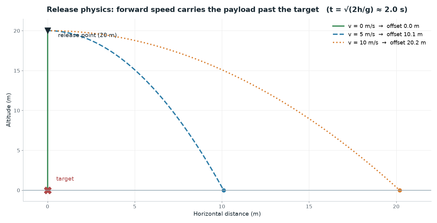
Here is the part we missed on our first attempt. At the moment of release the payload carries the aircraft's horizontal velocity, and it keeps traveling at that speed all the way down.
Fall time:
t = sqrt(2h / g)Horizontal drift:
x = v_ground × tVertical impact speed:
v_z = g × t
A concrete example, at our flight altitude:
h= 20 m,g= 9.81 m/s²,v_ground= 5 m/s
t = sqrt(2 × 20 / 9.81) = sqrt(4.08) = 2.02 s
x = 5 × 2.02 = 10.1 m
v_z = 9.81 × 2.02 = 19.8 m/s
So a payload you release from 20 meters while passing over at 5 m/s lands 10 meters beyond the release point. You have to issue the release command 10 meters short of the target. The same calculation gives 6.1 m at 3 m/s and 16.2 m at 8 m/s; horizontal drift scales linearly with speed and with the square root of altitude.
The v_ground here is ground speed (read from GPS), not airspeed. In wind, with the aircraft crabbing, the two diverge noticeably; put the wrong one into the formula and the error is measured in meters.
Drag and wind
The formulas above ignore drag. We can check how much error that costs us against the terminal velocity:
v_t = sqrt( 2mg / (rho × Cd × A) )0.5 L water bottle:
m= 0.5 kg,A≈ 0.0044 m²,Cd≈ 0.9,rho= 1.225 kg/m³
v_t = sqrt(9.81 / 0.00485) ≈ 45 m/s
Our impact speed is 19.8 m/s, less than half of terminal velocity. Drag is a small effect in that regime: for a dense, compact payload we would expect the vacuum approximation to overestimate horizontal drift by a few percent, meaning the real impact point sits slightly short of the calculated one. With light, bulky payloads (foam, cardboard, a package under a parachute) that gap grows fast and the formula stops being usable; at that point experimental calibration is mandatory.
Wind has two separate effects, and the bigger one is usually the one you don't expect. Direct wind drift on the falling payload is limited for a dense object over a ~2 second fall. The real source of error is the aircraft itself: position-hold error grows in wind, ground speed fluctuates, and the actual speed at the moment of release differs from what you planned. With light, bulky payloads the ranking flips and drift on the payload becomes dominant.
Ways to improve accuracy
The cleanest way to zero out horizontal drift is to zero out v_ground. Stop over the target (holding position in LOITER or GUIDED) and release there, and x = 0; all that is left is position error plus wind drift. The price is time: settling into a stable hover eats tens of seconds.
Lowering the release altitude helps on two channels at once: t shrinks (less drift) and the wind has less time to act. Releasing from 10 m instead of 20 m brings fall time down from 2.02 s to 1.43 s and drift at 5 m/s down from 10.1 m to 7.1 m.
Centering on the target with computer vision removes the dependence on the accuracy of the GPS coordinate. Take the detection from the gimbal camera (our YOLO training guide), convert it into an offset from the center of the image and apply a position correction, and you will still hit the target even if its coordinate is off by a few meters.
Finally, measure your latency budget. Whatever the total time of the detection → decision → MAVLink command → FC processing → servo travel chain turns out to be, the aircraft keeps covering ground for that entire time:
latency drift = v_ground × t_latency5 m/s and 0.3 s of total latency → 1.5 m of additional error
The servo's own travel time is a measurable part of that budget; account for the s/60° figure from the datasheet. Do not use a default number without measuring your own chain.
Our result
Across the autonomous drops we flew with our SUAS 2026 aircraft, the water bottle we released from roughly 20 meters landed an average of 5 meters from the target. The servo latch mechanism opened on every attempt; the remaining error was the sum of ground-speed uncertainty at the moment of release, GPS position error and the latency budget. For the next iteration we are moving to releasing from a hover and centering the target with the camera.
Common pitfalls
Ignoring forward speed. This is the most expensive mistake of them all. Release directly over the target and the payload lands 10 meters past it; apply the formula.
Using airspeed instead of ground speed. In wind the two diverge, and the difference turns straight into meters of miss.
Making the servo carry the load. An arm that carries the payload directly needs an order of magnitude more torque than a shear-pin latch; the servo gets bigger, heavier and thirstier.
Nylon gears. Under vibration and landing shock the gears strip, and you usually notice it right when you lose the payload.
The payload snagging. The latch opens but the payload catches on the airframe, on a cable or on its own packaging and falls late. Test the mechanism on the ground, over and over, with the payload at its exact size and exact weight, at the attitudes the aircraft actually flies (pitched forward, banked).
Trying to power the servo rail from the autopilot. A Pixhawk does not feed the servo rail; use a separate BEC and keep the voltage below 5.7 V.
SERVOx_FUNCTIONconflicts. If another function is assigned to the output,DO_SET_SERVOis silently rejected; read theCOMMAND_ACK.
Practical summary
Pick the mechanism to fit the mission: rugged payload + time pressure → servo latch; fragile payload + gentle landing → winch; repeated pick-and-place → EPM. Use a parachute only if you can afford to give up accuracy.
Run the torque calculation and then fix the geometry:
T = n × m × g × r, then design a latch that transfers the payload into the structure to cutrand the torque you need. Metal gears, a safety factor of 2–3.Bake the ballistics into the mission plan:
t = sqrt(2h/g),x = v_ground × t. Put the release waypointxshort of the target, and takev_groundfrom GPS.Separate the power: a dedicated BEC for the servo, the 4.1–5.7 V range, a voltage measurement under load, ground testing with the propellers off.
Improve accuracy one step at a time: the forward-speed correction first, then a lower release altitude, then releasing from a hover, and vision-based centering last. Validate every step in SITL and then measure it in the field with repeated drops.
NEIGHBOURS